https://zhuanlan.zhihu.com/p/534267979
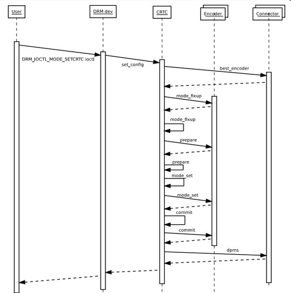
2.4 DRM Mode Setting Sequence Diagram
1.显示子系统(DSS)概述
显示子系统是显示输出相关软件硬件的统称,它包括VOP 和 RGB 、BT1120、BT656、I8080、LVDS、MIPI DSI、EDP、DP、HDMI等显示信号输出以及与之对应的软件驱动。
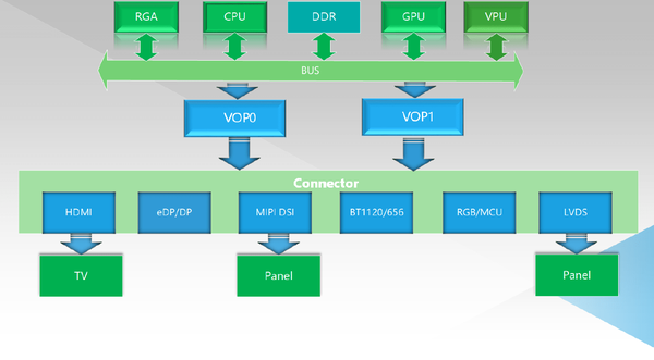
显示子系统硬件架构图之 VOP1.0 显示系统架构
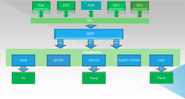
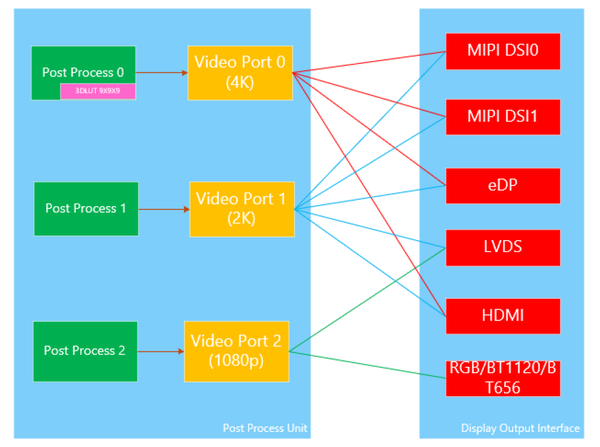
显示子系统硬件架构图之 VOP2.0 显示系统架构
上面的DSS框图,整个显示通路最后端,由RGA、GPU、VPU组成显示图形加速模块、他们是针对图形处理优化设计的硬件IP,能够高效的进行图形的生成和进一步处理(例如,GPU通过OpenGL功能提供图像渲染功能,RGA可以对图像数据进行缩放、旋转、合成等2D处理,VPU可以高效的进行视频解码),从而减轻CPU负担。
经过这些图像加速模块处理后的数据会放在DDR中,然后VOP读取,根据应用需求进行Alpha叠加,颜色空间转换、gamma矫正、HDR转换处理等,再发送到对应的显示接口模块(HDMI/DP/DSI/RGB/LVDS),这些接口模块会把接受收到的数据转换成符合给自协议的数据流,发送到显示器或者屏幕,呈现在最终的用户眼前。
VOP1.0是多用户VOP方式来显示多屏幕显示,即正常情况下,一个VOP在同一时刻只能输出一路独立的显示时序,驱动一个屏幕显示独立的内容。如果需要实现双屏幕显示,则需要两个VOP来实现。
VOP2.0采用统一显示架构,即整个SOC上只存在一个VOP,但是在VOP的后端设计多路独立的Video Port(简称VP)输出接口,这些VP能够独立同时独立工作,并且输出相关独立的显示时许。
2.DRM概述
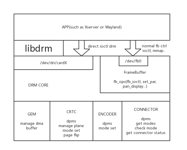
DRM全程是Direct Rendering Manger,进行显示输出管理 、buffer分配 、帧缓冲 。对应的userspace库libdrm,libdrm库提供了一系列友好的控制封装,是用户可以进行显示的控制和buffer申请。DRM设备节点为"/dev/dri/cardX", X为0-15的数值,默认使用的是“/dev/dri/card0”。
2.1基本概念
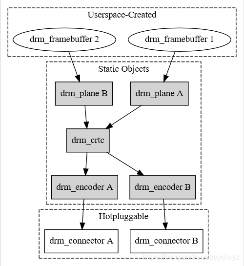
DRM Direct Rendering Manager Framewrok
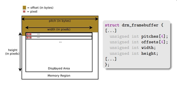
framebuffer
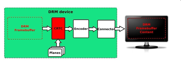
CRTC
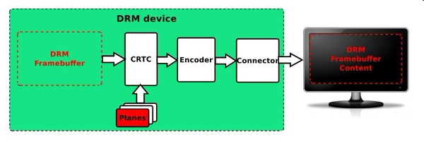
Planes
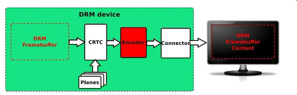
Encoder
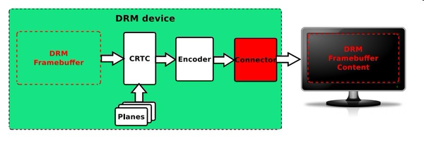
Connector
基本概念 说明 CRTC(Cathode Ray Tube Controller) 阴极射线管控制器,显示控制器,内部VOP模块或者VOP2中Video Port的抽象 Plane 图层,SoC内部VOP模块win图层的抽象 Encoder 输出转换器(编码器),指的是RGB、LVDS、DSI、eDP、DP、HDMI、CVBS、VGA等显示接口 Connector 连接器,指的是encoder和panel之间交互的接口部分 Bridge 桥接设备,一般用于注册Encoder后面另外再转接芯片,如DSI2HDMI转换芯片 Panel 泛指屏幕,各种LCD显示设备的抽象 GEM DRM下buffer管理和分配,类似ION、DMA BUFFER
CRTC常用行为 :
DPMS(Display Power Mange System) 电源状态管理(crtc_funcs-dpms) 将Framebuffer转换成标准的LCDC Timing,其实就是一帧图像刷新的过程(crtc_funcs->mode_set) 帧切换,即在vblank消影期间,切换framebuffer(crtc_funcs->page_flip) gamma校正值调整(crtc_funcs->gamma_set) ENCODER的常用行为如下 :
DPMS(Display Power Manage System)电源状态管理(encoder_functions->dpms) 将VOP输出的LCDC Timing 打包成对应接口时序 HDMI TMDS/... (encoder_funcs->mode_set) Connector的常用行为如下 :
获取上报的热插拔 Hotplug 状态 读取并解析屏幕(Panel)的EDID信息
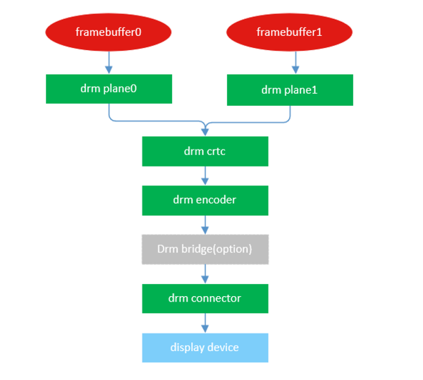
2.2显示通路
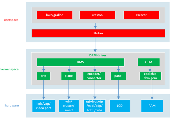
HDMI output resolution 1920x1080, Linux DRM/KMS kernel Component
显示通络
2.3 drm驱动和libdrm的交互过程
交互过程
2.4 DRM Mode Setting Sequence Diagram
Drm Mode Setting Sequence Diagram
3.驱动程序
3.1uboot驱动程序
显示驱动在 U-Boot 中主要提供开机 logo 显示和充电界面显示这两个功能。
3.2 kernel驱动
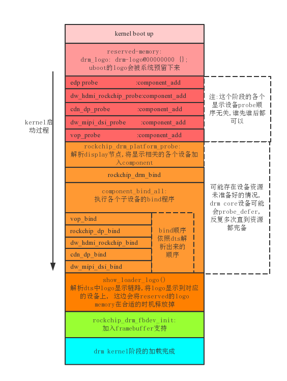
驱动加载顺序
驱动加载过程
需要注意的是,DRM驱动时一系列相关模块的驱动的结合,他包含了backlight,panel,rgb,lvds,dsi,edp,hdmi,vop等等显示通路上的依赖模块。只有这些相互依赖的模块都加载完整,整个drm系统才算启动完成。
因为这些复杂的依赖关系,在 drm 系统初始化的过程中,可能会出现某个资源暂时未就绪,而导致某个模块暂时无法顺利加载的情况,为了解决这种问题,drm 驱动利用了 Linux 驱动 中的 deferred probe 机制,当发现某个依赖的资源未就绪的时候,驱动返回 -EPROBE_DEFER(-517) , 然后退出。Linux kernel 会在稍后再次尝试加载这个驱动,直到依赖的资源就绪,驱动顺利加载为止。
例子:
[1.747190] rockchip-drm display-subsystem: bound fdd90000.vop (ops vop2_component_ops)
[1.747877] dwhdmi-rockchip fde80000.hdmi: registered ddc I2C bus driver
[1.748022] rockchip-drm display-subsystem: bound fde80000.hdmi (ops
dw_hdmi_rockchip_ops)
[1.748676] dwhdmi-rockchip fdea0000.hdmi: registered ddc I2C bus driver
[1.748807] rockchip-drm display-subsystem: bound fdea0000.hdmi (ops
dw_hdmi_rockchip_ops)
[1.748840] dw-mipi-dsi2 fde20000.dsi: [drm:dw_mipi_dsi2_bind] *ERROR* Failed to find
panel or bridge: -517
[1.755174] panel-simple-dsi fde20000.dsi.0: failed to get power regulator: -517
[1.759296] brd: module loaded
[1.764374] loop: module loaded
[1.764528] zram: Added device: zram0
[1.764698] system_heap: orders[0] = 6
[2.248871] imx415 5-001a: supply dovdd not found, using dummy regulator
[2.416673] rockchip-drm display-subsystem: bound fdd90000.vop (ops vop2_component_ops)
[2.418711] dwhdmi-rockchip fde80000.hdmi: registered ddc I2C bus driver
[2.420336] rockchip-drm display-subsystem: bound fde80000.hdmi (ops
dw_hdmi_rockchip_ops)
[2.421725] dwhdmi-rockchip fdea0000.hdmi: registered ddc I2C bus driver
[2.422291] rockchip-drm display-subsystem: bound fdea0000.hdmi (ops
dw_hdmi_rockchip_ops)
[2.422318] dw-mipi-dsi2 fde20000.dsi: [drm:dw_mipi_dsi2_bind] *ERROR* Failed to find
panel or bridge: -517
[2.433888] input: adc-keys as /devices/platform/adc-keys/input/input3
[2.466237] rockchip-drm display-subsystem: bound fdd90000.vop (ops vop2_component_ops)
[2.468705] dwhdmi-rockchip fde80000.hdmi: registered ddc I2C bus driver
[2.469751] rockchip-drm display-subsystem: bound fde80000.hnd fde20000.dsi (ops
dw_mipi_dsi2_ops)
[2.472282] rockchip-drm display-subsystem: bound fde50000.dp (ops dw_dp_component_ops)
[2.472319] rockchip-drm display-subsystem: bound fde60000.dp (ops dw_dp_component_ops)
[2.531892] rockchip-drm display-subsystem: [drm] fb0: rockchipdrmfb frame buffer device
[2.532850] [drm] Initialized rockchip 3.0.0 20140818 for display-subsystem on minor 0
从上面的 log 我们可以看到,在第 6 行和第 18 行,mipi dsi 驱动因为找不到 panel 或者 bridge 这个依赖资源,而返回-EPROBE_DEFER 退出,一直到第 23 行,dsi 驱动获取到依赖的资源 bind 成功,最终看到整个 drm 驱动完成加载的标准 log。
DTS配置:
在一颗SoC上,可能由多个VOP,HDMI,eDP,DP,MIPI,Panel模块,根据具体产品定义,一款产品可能只需要使用其中一部分模块组成显示通路。具体使用那些模块,以及这些模块之间如何衔接通过dts配置。
在每一个支持drm显示功能的SoC的核心dts里面,都会由如下display_subsystem节点:
display_subsystem: display-subsystem {
                compatible = "rockchip,display-subsystem";
                memory-region = <&drm_logo>, <&drm_cubic_lut>;
                memory-region-names = "drm-logo", "drm-cubic-lut";
                ports = <&vop_out>;
                devfreq = <&dmc>;
                route {
                     route_dsi0: route-dsi0 {
                         status = "disabled";
                         logo,uboot = "logo.bmp";
                         logo,kernel = "logo_kernel.bmp";
                         logo,mode = "center";
                         charge_logo,mode = "center";
                         connect = <&vp0_out_dsi0>;
                      };
                      route_dsi1: route-dsi1 {
                          status = "disabled";
                          logo,uboot = "logo.bmp";
                          logo,kernel = "logo_kernel.bmp";
                          logo,mode = "center";
                          charge_logo,mode = "center";
                          connect = <&vp0_out_dsi1>;
           };
           route_edp: route-edp {
             status = "disabled";
             logo,uboot = "logo.bmp";
             logo,kernel = "logo_kernel.bmp";
             logo,mode = "center";
             charge_logo,mode = "center";
             connect = <&vp0_out_edp>;
           };
           route_hdmi: route-hdmi {
             status = "disabled";
             logo,uboot = "logo.bmp";
             logo,kernel = "logo_kernel.bmp";
             logo,mode = "center";
             charge_logo,mode = "center";
             connect = <&vp1_out_hdmi>;
           };
           route_lvds: route-lvds {
             status = "disabled";
             logo,uboot = "logo.bmp";
             logo,kernel = "logo_kernel.bmp";
             logo,mode = "center";
             charge_logo,mode = "center";
             connect = <&vp1_out_lvds>;
           };
           route_rgb: route-rgb {
             status = "disabled";
             logo,uboot = "logo.bmp";
             logo,kernel = "logo_kernel.bmp";
             logo,mode = "center";
             charge_logo,mode = "center";
             connect = <&vp2_out_rgb>;
         };
    };
};
该节点控制drm_drv.c驱动的加载。
vop节点
vop节点描述了VOP硬件资源,控制vop驱动的加载drm_vop.c drm_vop2.c,它描述了如下的显示通路连接关系:
VoP节点
vop_out: ports节点描述vop,vop0/1/2对应vop上video port 0/1/2三个独立的输出通路。
vp0/1/2:port下的endpoint描述的时VP和显示接口的连接关系,以上面的dts描述为例:vp0节点下有
vp0_out_dsi0,vp0_out_dsi1,vp0_out_edp,vp0_out_hdmi四个节点,说明vp0可以和dsi0、dsi1、
edp、hdmi、四个显示接口连接。
每个endpoint通过remote-endpoint属性和对应的显示接口组成一个连接通路,比如和hdmi显示接口的连接:
hdmi: hdmi@fe0a0000 {
      compatible = "rockchip,rk3568-dw-hdmi";
      ...
      status = "disabled";
      ports{
          ....
          port@0 {
              reg = <0>;
              ....
              hdmi_in_vp0: endpoint@0
              {
                  reg = <0>;
                  remote-endpoint = <&vp0_out_hdmi>;
                  status = "disabled";
               };
               hdmi_in_vp1: endpoint@1 {
                  reg = <1>;
                  remote-endpoint = <&vp1_out_hdmi>;
                  status = "disabled";
               }
          }
      };
};
希望 HDMI 连接在 vp0 上,则 dts 中需要做如下设置:
&hdmi {
     status = "okay";
};
&hdmi_in_vp0 {
     status = "okay";
};
&hdmi_in_vp1 {
     status = "disabled";
};
&route_hdmi {
     status = "okay";
     connect = <&vp0_out_hdmi>;
};
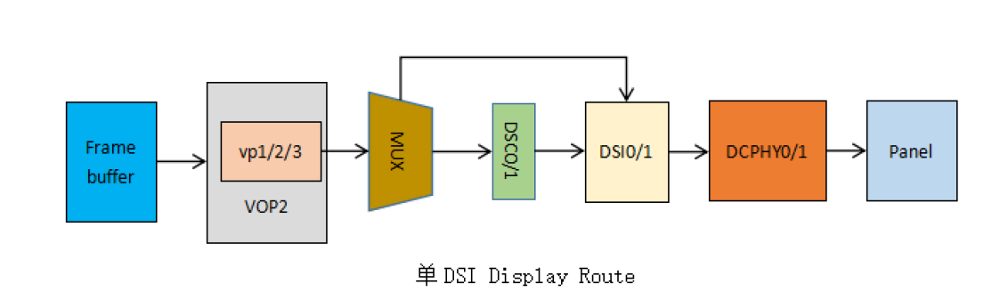
单路DSI
单路DSI display interface和 panel之间的关联
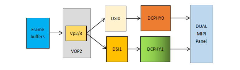
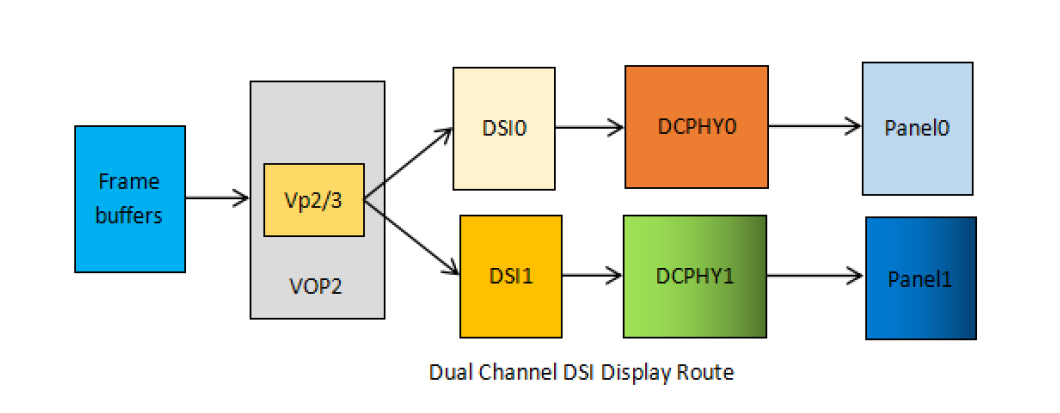
双通道DSI
MODE1
MODE2
3.3 清单文件
驱动 文件清单 Core drivers/gpu/drm/rockchip/rockchip_drm_drv.c framebuffer drivers/gpu/drm/rockchip/rockchip_drm_fb.c gem drivers/gpu/drm/rockchip/rockchip_drm_gem.c vop drivers/gpu/drm/rockchip/rockchip_drm_vop.c lvds drivers/gpu/drm/rockchip/rockchip_lvds.c rga drivers/gpu/drm/rockchip/rockchip_drm_rga.c mipi drivers/gpu/drm/rockchip/dw-mipi-dsi.c hdmi drivers/gpu/drm/rockchip/inno_hdmi.c edp drivers/gpu/drm/rockchip/analogix_dp-rockchip.c dp drivers/gpu/drm/rockchip/cdn-dp-core.c
3.4 component框架
框架代码:drivers/base/component.c
功能:
component framework作者Russell King对该机制的描述:
Subsystems such as ALSA, DRM and others require a single card-level
device structure to represent a subsystem.  However, firmware tends to
describe the individual devices and the connections between them.
Therefore, we need a way to gather up the individual component devices
We do this in DT by providing a “superdevice” node which specifies
imx-drm {
        compatible = "fsl,drm";
        crtcs = <&ipu1>;
        connectors = <&hdmi>;
};
The superdevice is declared into the component support, along with the
When any of the components or superdevice are removed from the system,
在dts中, 有一个总的设备节点, 所有的子设备信息都通过dts描述关联起来, 这样系统 开机后, 就能统一的管理各个设备.
3.5 DRM主设备(主驱动)
设备device tree :
display_subsystem: display-subsystem {
compatible: Should be “rockchip,display-subsystem” ports: Should contain a list of phandles pointing to display interface port代码位置 :
drivers/gpu/drm/rockchip/rockchip_drm_drv.c 主体结构:
static struct drm_driver rockchip_drm_driver = { 3.6 VOP驱动 代码位置:
drivers/gpu/drm/rockchip/rockchip_drm_vop.c 结构介绍 :
struct vop; 寄存器读写 :
为了兼容各种不同版本的vop, vop驱动里面使用了寄存器级的抽象, 由一个结构体来保 示例:
图层接口 :
static const struct drm_plane_helper_funcs plane_helper_funcs = {
vop接口:
static const struct drm_crtc_helper_funcs vop_crtc_helper_funcs = {
3.7 特殊DRM配置
DRM_IGNORE_IOTCL_PERMIT
这个是由我们添加的, 用于解决android上其他进程模块无法访问drm的问题,目前仅使用在android项目上
CONFIG_DRM_FBDEV_EMULATION
使能该功能后, drm将模拟一个framebuffer设备, 可用于基于fbdev的基础显示框架.
CONFIG_DRM_LOAD_EDID_FIRMWARE
allow loading an EDID as firmware to override broken monitor
Broken monitors and/or broken graphic boards may send erroneous or no
This patch allows to specify an EDID data set to be used instead of
It is also possible to restrict the usage of a specified EDID data set
The built-in data sets are
1024x768 edid/1024x768.bin
They are ignored, if a file with the same name is available in the
The built-in EDID data sets are based on standard timings that may not
3.8 DRM devices Tree解析
总的drm device结构如下:
// rockchip drm core 设备
// 显示控制器vop驱动
// edp驱动
edp屏驱动
ports {
    panel_in_edp: endpoint {
        remote-endpoint = <&edp_out_panel>;
    };
};
};
4.屏相关配置
4.1 屏幕的几种配置方式
通用屏驱动:
drivers/gpu/drm/panel/panel-simple.c
device-tree:
Required properties:
Optional properties:
compatible: value maybe one of the following
ddc-i2c-bus: phandle of an I2C controller used for DDC EDID probing
enable-gpios: GPIO pin to enable or disable the panel
backlight: phandle of the backlight device attached to the panel
Required properties when compatible is “simple-panel” or “simple-panel-dsi”:
display-timings: see display-timing.txt for information Optional properties:
delay,prepare: the time (in milliseconds) that it takes for the panel to delay,enable: the time (in milliseconds) that it takes for the panel to delay,disable: the time (in milliseconds) that it takes for the panel to delay,unprepare: the time (in milliseconds) that it takes for the panel bus-format: Optional properties when compatible is a dsi devices:
dsi,flags: dsi operation mode related flags
dsi,format: pixel format for video mode
dsi,lanes: number of active data lanes
屏幕的配置方式一:使用短字符串匹配写死的timing
1.把timings写在drivers/gpu/drm/panel/panel-simple.c中, 直接以短字符匹配, 该方式为upstream推荐的使用方式.
DeviceTree:
panel: panel { drivers/gpu/drm/panel/panel-simple.c:
static const struct drm_display_mode lg_lp097qx1_spa1_mode = { 屏配置方式二: 直接将timing写在dts文件中
2.把使用display-timings结构, 直接把timing写在dts文件中, 这类适用于简单的屏配置
panel: panel { display-timings {
native-mode = <&timing0>;
timing0: timing0 {
clock-frequency = <160000000>;
hactive = <1200>;
vactive = <1920>;
hback-porch = <21>;
hfront-porch = <120>;
vback-porch = <18>;
vfront-porch = <21>;
hsync-len = <20>;
vsync-len = <3>;
hsync-active = <0>;
vsync-active = <0>;
de-active = <0>;
pixelclk-active = <0>;
};
};
};
屏配置方式三: 使用edid
3.不填写任何timing, 直接使用edid来获取timing
panel: panel { Document:
Documentation/devicetree/bindings/display/panel/simple-panel.txt 4.2 eDP屏幕点亮步骤 步骤一:
参考《屏配置的几个方式》章节,先使用edid的方式,在dts里面写入:
panel: panel { 如果屏的edid正常, power, gpio, backlight配置正常,应该就能看到显示了
步骤二:
由于屏的edid是有机率损坏的,做产品是有风险的,所以建议把timing写死到代码里面:
完成步骤一后,可以从uboot串口上获取当前的屏的信息:
Maximum visible display size: 26 cm x 17 cm 参考《屏配置的几个方式》章节, 屏配置方式一, 将该timing写死到kernel中.
4.3 LVDS屏幕配置
驱动:
drivers/gpu/drm/rockchip/rockchip_lvds.c
参考配置:
arch/arm64/boot/dts/rockchip/rk3368-sheep-lvds.dts
文档:
Documentation/devicetree/bindings/video/rockchip-lvds.txt:
Required properties:
compatible: matching the soc type, one of
“rockchip,rk3288-lvds”; “rockchip,rk33xx-lvds”; reg: physical base address of the controller and length
reg-names: the name to indicate register. example:
“mipi_lvds_phy”: lvds phy register, this’s included in the MIPI phy module “mipi_lvds_ctl”: lvds control register, this’s included in the MIPI clocks: must include clock specifiers corresponding to entries in the
clock-names: must contain “pclk_lvds”
avdd1v0-supply: regulator phandle for 1.0V analog power
avdd1v8-supply: regulator phandle for 1.8V analog power
avdd3v3-supply: regulator phandle for 3.3V analog power
rockchip,grf: phandle to the general register files syscon
rockchip,data-mapping: should be “vesa” or “jeida”,
rockchip,data-width : should be <18> or <24>;
rockchip,output: should be “rgb”, “lvds” or “duallvds”,
Optional properties
pinctrl-names: must contain a “default” entry. pinctrl-0: pin control group to be used for this controller. pinctrl-1: pin control group to be used for gpio. Required nodes:
The lvds has two video ports as described by
video port 0 for the VOP inputs video port 1 for either a panel or subsequent encoder Example:
For Rockchip RK3288:
lvds: lvds@ff96c000 {
    compatible = "rockchip,rk3288-lvds";
    rockchip,grf = <&grf>;
    reg = <0xff96c000 0x4000>;
    clocks = <&cru PCLK_LVDS_PHY>;
    clock-names = "pclk_lvds";
    avdd1v0-supply = <&vdd10_lcd>;
    avdd1v8-supply = <&vcc18_lcd>;
    avdd3v3-supply = <&vcca_33>;
    rockchip,data-mapping = "jeida";
    rockchip,data-width = <24>;
    rockchip,output = "rgb";
    ports {
        #address-cells = <1>;
        #size-cells = <0>;

        lvds_in: port@0 {
            reg = <0>;

            lvds_in_vopb: endpoint@0 {
                reg = <0>;
                remote-endpoint = <&vopb_out_lvds>;
            };
            lvds_in_vopl: endpoint@1 {
                reg = <1>;
                remote-endpoint = <&vopl_out_lvds>;
            };
        };

        lvds_out: port@1 {
            reg = <1>;

            lvds_out_panel: endpoint {
                remote-endpoint = <&panel_in>;
            };
        };
    };
};
For Rockchip RK3368:
lvds: lvds@ff968000 {
compatible = "rockchip,rk33xx-lvds";
reg = <0x0 0xff968000 0x0 0x4000>, <0x0 0xff9600a0 0x0 0x20>;
reg-names = "mipi_lvds_phy", "mipi_lvds_ctl";
clocks = <&cru PCLK_DPHYTX0>, <&cru PCLK_MIPI_DSI0>;
clock-names = "pclk_lvds", "pclk_lvds_ctl";
power-domains = <&power RK3368_PD_VIO>;
rockchip,grf = <&grf>;
pinctrl-names = "lcdc", "gpio";
pinctrl-0 = <&lcdc_lcdc>;
pinctrl-1 = <&lcdc_gpio>;
ports {
...
};
};</code></pre></div><h2 id="h_534267979_19" data-into-catalog-status="">5.开机LOGO配置</h2><p data-pid="Ip-ervB7">参考配置: arch/arm64/boot/dts/rockchip/rk3399-android.dtsi</p><h3 id="h_534267979_20" data-into-catalog-status="">5.1DeviceTree 解析:</h3><div class="highlight"><pre><code class="language-text">reserved-memory {
//在reserved memory划一块内存做为logo使用
drm_logo: drm-logo@00000000 {
compatible = "rockchip,drm-logo";
//size填0, uboot将会根据实际logo占用buffer的大小分配
//用户无需填写
reg = <0x0 0x0 0x0 0x0>;
};
};
&display_subsystem {
//drm驱动将解析drm_logo的buffer, 用于logo显示
memory-region = <&drm_logo>;
route {
    //每一组route_xxx代表一路显示输出
    route_hdmi: route-hdmi {

        //在uboot loader阶段所使用的图片, 名称可根据resource.img打包的logo图片名称定义.
        //当该属性留空或者指定的图片找不到时, uboot将不显示
        logo,uboot = "logo.bmp";

        //在uboot loader阶段所使用的图片, 名称可根据resource.img打包的logo图片名称定义.
        //当该属性留空或者指定的图片找不到时, uboot将不显示
        logo,kernel = "logo_kernel.bmp";

        //支持两种显示模式: "fullscreen"全屏和"center'居中
        logo,mode = "fullscreen";

        //充电logo, 支持两种显示模式: "fullscreen"全屏和"center'居中
        charge_logo,mode = "center";

        //指定具体的显示通路, 如下, 为hdmi使用vopb输出
        connect = <&vopb_out_hdmi>;
    };
    route_mipi: route-mipi {
        logo,uboot = "logo_mipi.bmp";
        logo,kernel = "logo_kernel_mipi.bmp";
        logo,mode = "fullscreen";
        charge_logo,mode = "center";
        connect = <&vopb_out_mipi>;
    };
    route_edp: route-edp {
        logo,uboot = "logo_edp.bmp";
        logo,kernel = "logo_kernel_edp.bmp";
        logo,mode = "fullscreen";
        charge_logo,mode = "center";
        connect = <&vopb_out_edp>;
    };
};
};
5.2 开机logo 双屏异显配置
arch/arm64/boot/dts/rockchip/rk3399-android.dtsi
两路输出显示不同的内容:
如下, route_hdmi使用logo_hdmi.bmp, route_mipi使用logo_mipi.bmp
&display_subsystem { logo,uboot = "logo_hdmi.bmp";
logo,kernel = "logo_kernel_hdmi.bmp";
connect = <&vopl_out_hdmi>;
};
route_mipi: route-mipi {
logo,uboot = "logo_mipi.bmp";
logo,kernel = "logo_kernel_mipi.bmp";
logo,mode = "fullscreen";
charge_logo,mode = "center";
connect = <&vopb_out_mipi>;
};
};
};
hdmi和mipi就将显示不同的图片内容.
两路输出同时显示:
不同route使用不同的vop即可实现显示的独立. 例如:
route_hdmi的connect配置成vopl_out_hdmi,
hdmi和edp就将使用不同的vop独立显示
5.3 多屏抢占及热插拔
&display_subsystem { route_mipi: route-mipi {
connect = <&vopb_out_mipi>;
};
route_edp: route-edp {
connect = <&vopl_out_edp>;
};
};
抢占:
oute的节点是有顺序优先关系的, 如上, route_hdmi在route_mipi之前, 且它们都使用vopb做为显示输出, 当hdmi和mipi同接入时, hdmi会先将vopb抢走, 这样mipi就分配不到vop了, 现象为: hdmi显示, mipi不显示。
热拔插
如上抢占内容可知, 当hdmi插入时, 现象为hdmi显示, mipi不显
但当hdmi处于拔出状态时, route_hdmi这一路将不会工作, 也即可以实现: hdmi不显示, mipi显示.
由此实现同一配置, 插入hdmi和拔出hdmi启动过程通路状态不同.
5.4支持的logo格式
格式 生成方式 8bit rle8 bmp convert -compress rle -colors 256 logo_old.bmp logo_new.bmp 24 bit bmp 非压缩 32 bit bmp 非压缩
6.调试手段
6.1 查看dump当前显示状态
command:
cat /sys/kernel/debug/dri/0/summary
打印信息 :
vop name: ff900000.vop status=active
6.2查看dump当前drm使用的buffer
命令:
cat /sys/kernel/debug/dri/0/mm_dump
打印信息:
0x0000000000000000-0x00000000004f2000: 5185536: used
6.3 modetest使用指南
modetest是libdrm源码自带的调试工具, 可以对drm进行一些基础的调试.
android平台:
mmm external/libdrm/tests
linux平台 - ARM64
git clone git://anongit.freedesktop.org/mesa/drm && cd drmpwd/out
modetest帮助信息:
(shell)# modetest -h
使用案例:
modetest不带参(有非常多的打印,这边截取部分关键的):
//由于rockchip driver的一些配置未upstream到libdrm上, 所以从libdrm upstream
如上modetest -M rockchip 的信息,我们知道当前系统有两个vop, 有两个输出设备:
测试显示输出: 测试显示输出时要把当前系统其他的显示关掉, 因为drm只能允许一个显示输出程序.
android: adb shell stop
显示输出命令
(shell)# modetest -M rockchip -s 72@27:1440x900 -v
屏幕上即可看到闪烁的彩条显示,
6.4 设置DRM的调试log等级
sys结点位置: /sys/module/drm/parameters/debug
debug:Enable debug output, where each bit enables a debug category.
示例: echo 0x0c > /sys/module/drm/parameters/debug
6.5 查看显示时钟
查看显示时钟:
(shell)# cat /sys/kernel/debug/clk/clk_summary | grep vop
需要关注的显示时钟为:
dclk_vop :
即pixel clock, 像素时钟, 该时钟由具体的显示timing决定, 如果dclk不正确, 可能导致fps不对或直接不显示. edp, mipi, lvds等显示接口对应dclk的容忍性较好, 有些偏差也不影响正常显示 . 但hdmi, dp等高清显示接口, 是有严格要求的, 这类显示接口的频率要给的很精准 .
aclk_vop:
如果该时钟频率太低, 可能会导致显示出现抖动, 另外如果aclk 没有使能的话, 访问vop的寄存器也可能引发总线挂死
hclk_vop:
如果该时钟未使能, 不能访问vop的寄存器, 一但访问vop寄存器, 会造成总线挂死.
6.6 查看当前GPIO的配置
(shell)# cat /sys/kernel/debug/gpio
GPIOs 0-31, platform/pinctrl, gpio0:
drm panel驱动默认使用enable做为屏的gpio使能脚, 所以这边重点看一下enable的状态, 是否与预期的一致.
6.7 强行使能显示设备
不管hdmi接没接, 强行使能hdmi
echo on > /sys/devices/platform/display-subsystem/drm/card0/card0-HDMI-A-1/status
关闭hdmi
echo off > /sys/devices/platform/display-subsystem/drm/card0/card0-HDMI-A-1/status
监测hdmi插拔,正常情况以就是在这个状态
echo detect > /sys/devices/platform/display-subsystem/drm/card0/card0-HDMI-A-1/status
本文内容由网友自发贡献,版权归原作者所有,本站不承担相应法律责任。如您发现有涉嫌抄袭侵权的内容,请联系:hwhale#tublm.com(使用前将#替换为@)