前面耽搁了几天,今天终于把CH347 SPI接口调试好了。
CH347动态库中SPI接口函数如下:
typedef struct _SPI_CONFIG{
	UCHAR           iMode;                 // 0-3:SPI Mode0/1/2/3
	UCHAR           iClock;                // 0=60MHz, 1=30MHz, 2=15MHz, 3=7.5MHz, 4=3.75MHz, 5=1.875MHz, 6=937.5KHz,7=468.75KHz
	UCHAR			iByteOrder;            // 0=LSB first(LSB), 1=MSB first(MSB)
	USHORT          iSpiWriteReadInterval; // The SPI interface routinely reads and writes data command, the unit is uS
	UCHAR           iSpiOutDefaultData;    // SPI prints data by default when it reads data
	ULONG			iChipSelect;           // Piece of selected control, if bit 7 is 0, slice selection control is ignored, if bit 7 is 1, the parameter is valid: bit 1 bit 0 is 00/01 and CS1/CS2 pins are selected as low level active chip options respectively
	UCHAR           CS1Polarity;           // Bit 0: CS1 polarity control: 0: effective low level; 1: effective lhigh level;
	UCHAR           CS2Polarity;           // Bit 0: CS2 polarity control: 0: effective low level; 1: effective lhigh level;
	USHORT          iIsAutoDeativeCS;      // Whether to undo slice selection automatically after the operation is complete
	USHORT          iActiveDelay;          // Set the latency for read/write operations after slice selection,the unit is us
	ULONG           iDelayDeactive;        // Delay time for read and write operations after slice selection is unselected,the unit is us
}mSpiCfgS,*mPSpiCfgS;

/***************SPI********************/
// SPI Controller Initialization
BOOL	WINAPI	CH347SPI_Init(ULONG iIndex,mSpiCfgS *SpiCfg);

// Get SPI controller configuration information
BOOL    WINAPI  CH347SPI_GetCfg(ULONG iIndex,mSpiCfgS *SpiCfg);

// Before setting the chip selection status, call CH347SPI_Init to set CS
BOOL	WINAPI	CH347SPI_ChangeCS(ULONG			iIndex,         // Specify device number
								  UCHAR         iStatus);       // 0=Cancel the piece to choose,1=Set piece selected

// Set SPI slice selection
BOOL	WINAPI	CH347SPI_SetChipSelect(ULONG			iIndex,            // Specify device number
									   USHORT           iEnableSelect,     // The lower octet is CS1 and the higher octet is CS2. A byte value of 1= sets CS, 0= ignores this CS setting
									   USHORT           iChipSelect,       // The lower octet is CS1 and the higher octet is CS2. A byte value of 1= sets CS, 0= ignores this CS setting
									   ULONG            iIsAutoDeativeCS,  // The lower 16 bits are CS1 and the higher 16 bits are CS2. Whether to undo slice selection automatically after the operation is complete
									   ULONG            iActiveDelay,      // The lower 16 bits are CS1 and the higher 16 bits are CS2. Set the latency of read/write operations after chip selection, the unit is us
									   ULONG            iDelayDeactive);   // The lower 16 bits are CS1 and the higher 16 bits are CS2. Delay time for read and write operations after slice selection the unit is us

//SPI4 write data
BOOL	WINAPI	CH347SPI_Write(ULONG			iIndex,          // Specify device number
							   ULONG			iChipSelect,     // Slice selection control, when bit 7 is 0, slice selection control is ignored, and when bit 7 is 1, slice selection operation is performed
							   ULONG			iLength,         // Number of bytes of data to be transferred
							   ULONG			iWriteStep,      // The length of a single block to be read
							   PVOID			ioBuffer);       // Point to a buffer to place the data to be written out from MOSI

//SPI4 read data. No need to write data first, the efficiency is higher than that of the CH347SPI_WriteRead
BOOL	WINAPI	CH347SPI_Read(ULONG			iIndex,           // Specify device number
							  ULONG			iChipSelect,      // Slice selection control, when bit 7 is 0, slice selection control is ignored, and when bit 7 is 1, slice selection operation is performed
							  ULONG         oLength,          // Number of bytes to send
							  PULONG		iLength,          // Number of bytes of data to be read in
							  PVOID			ioBuffer);        // Points to a buffer that place the data to be written out from DOUT, return the data read in from DIN

// Handle SPI data stream 4-wire interface
BOOL	WINAPI	CH347SPI_WriteRead(ULONG			iIndex,       // Specify the device number
								   ULONG			iChipSelect,  // Selection control, if the film selection control bit 7 is 0, ignore the film selection control bit 7 is 1 and operate the film selection
								   ULONG			iLength,      // Number of bytes of data to be transferred
								   PVOID			ioBuffer );   // Points to a buffer that place the data to be written out from DOUT, return the data read in from DIN

//place the data to be written from MOSI, return the data read in from MISO
BOOL	WINAPI	CH347StreamSPI4(ULONG			iIndex,       // Specify the device number
								ULONG			iChipSelect,  // Film selection control, if bit 7 is 0, slice selection control is ignored.If bit 7 is 1, the parameter is valid:Bit 1 bit 0 is 00/01/10. Select D0/D1/D2 pins as low level active chip options respectively
								ULONG			iLength,      // Number of bytes of data to be transferred
								PVOID			ioBuffer );   // Points to a buffer, places data to be written out from DOUT, and returns data to be read in from DIN
要实现SPI通信,至少要用到CH347SPI_Init(ULONG iIndex,mSpiCfgS *SpiCfg) CH347SPI_Write(ULONG iIndex, ULONG iChipSelect, ULONG iLength, ULONG iWriteStep, PVOID ioBuffer) CH347SPI_Read(ULONG iIndex, ULONG iChipSelect, ULONG oLength, PULONG iLength, PVOID ioBuffer)这3个函数。
对这3个函数进行封装:
class SPIConfig(ctypes.Structure):
    _fields_ = [
        ("iMode", ctypes.c_ubyte),                      # 0-3: SPI Mode0/1/2/3
        ("iClock", ctypes.c_ubyte),                     # 0=60MHz, 1=30MHz, 2=15MHz, 3=7.5MHz,
        ("iByteOrder", ctypes.c_ubyte),                 # 4=3.75MHz, 5=1.875MHz, 6=937.5KHz, 7=468.75KHz
        ("iSpiWriteReadInterval", ctypes.c_ushort),     # Regular interval for SPI read/write commands, in microseconds
        ("iSpiOutDefaultData", ctypes.c_ubyte),         # Default output data when reading from SPI
        ("iChipSelect", ctypes.c_ulong),                # Chip select control. Bit 7 as 0 ignores chip select control,
                                                        # Bit 7 as 1 makes the parameters valid:
                                                        # Bit 1 and Bit 0 as 00/01 selects CS1/CS2 pin as the active low chip select.
        ("CS1Polarity", ctypes.c_ubyte),                # Bit 0: CS1 polarity control, 0: active low, 1: active high
        ("CS2Polarity", ctypes.c_ubyte),                # Bit 0: CS2 polarity control, 0: active low, 1: active high
        ("iIsAutoDeativeCS", ctypes.c_ushort),          # Automatically de-assert chip select after the operation is completed
        ("iActiveDelay", ctypes.c_ushort),              # Delay time for executing read/write operations after chip select is set, in microseconds
        ("iDelayDeactive", ctypes.c_ulong)              # Delay time for executing read/write operations after chip select is de-asserted, in microseconds
    ]

def spi_init(self, device_index: int, spi_config: SPIConfig) -> bool:
	"""
	Initialize the SPI Controller.

	Args:
		device_index (int): The device number.
		spi_config (SPIConfig): The configuration for the SPI controller.

	Returns:
		bool: True if initialization is successful, False otherwise.
	"""
	result = self.ch347dll.CH347SPI_Init(device_index, ctypes.byref(spi_config))
	return result

def spi_write(self, device_index: int, chip_select: int, write_data: bytes, write_step: int = 512) -> bool:
	"""
	SPI write data.

	Args:
		device_index (int): Device number.
		chip_select (int): Chip selection control. When bit 7 is 0, chip selection control is ignored.
							When bit 7 is 1, chip selection operation is performed.
		write_data (bytes): Data to write.
		write_step (int, optional): The length of a single block to be read. Default is 512.

	Returns:
		bool: True if successful, False otherwise.
	"""
	write_length = len(write_data)
	write_buffer = ctypes.create_string_buffer(write_data)
	result = self.ch347dll.CH347SPI_Write(device_index, chip_select, write_length, write_step, write_buffer)
	return result

def spi_read(self, device_index: int, chip_select: int, write_data: bytes, read_length: int) -> bytes:
	"""
	SPI read data.

	Args:
		device_index (int): Device number.
		chip_select (int): Chip selection control. When bit 7 is 0, chip selection control is ignored.
						When bit 7 is 1, chip selection operation is performed.
		write_data (bytes): Data to write.
		read_length (int): Number of bytes to read.

	Returns:
		bytes: Data read in from the SPI stream if successful, None otherwise.
	"""
	write_length = len(write_data)

	# Create ctypes buffer for write data
	write_buffer = ctypes.create_string_buffer(write_data)

	# Create ctypes buffer for read data
	read_buffer = ctypes.create_string_buffer(read_length)

	# Create combined buffer for read and write data
	combined_buffer = ctypes.create_string_buffer(write_buffer.raw[:write_length] + read_buffer.raw)

	result = self.ch347dll.CH347SPI_Read(device_index, chip_select, write_length, ctypes.byref(ctypes.c_ulong(read_length)), combined_buffer)

	if result:
		# Extract the read data from the combined buffer
		read_data = combined_buffer[:read_length]
		return bytes(read_data)
	else:
		return None
连接CH347和SPI Flash模块:
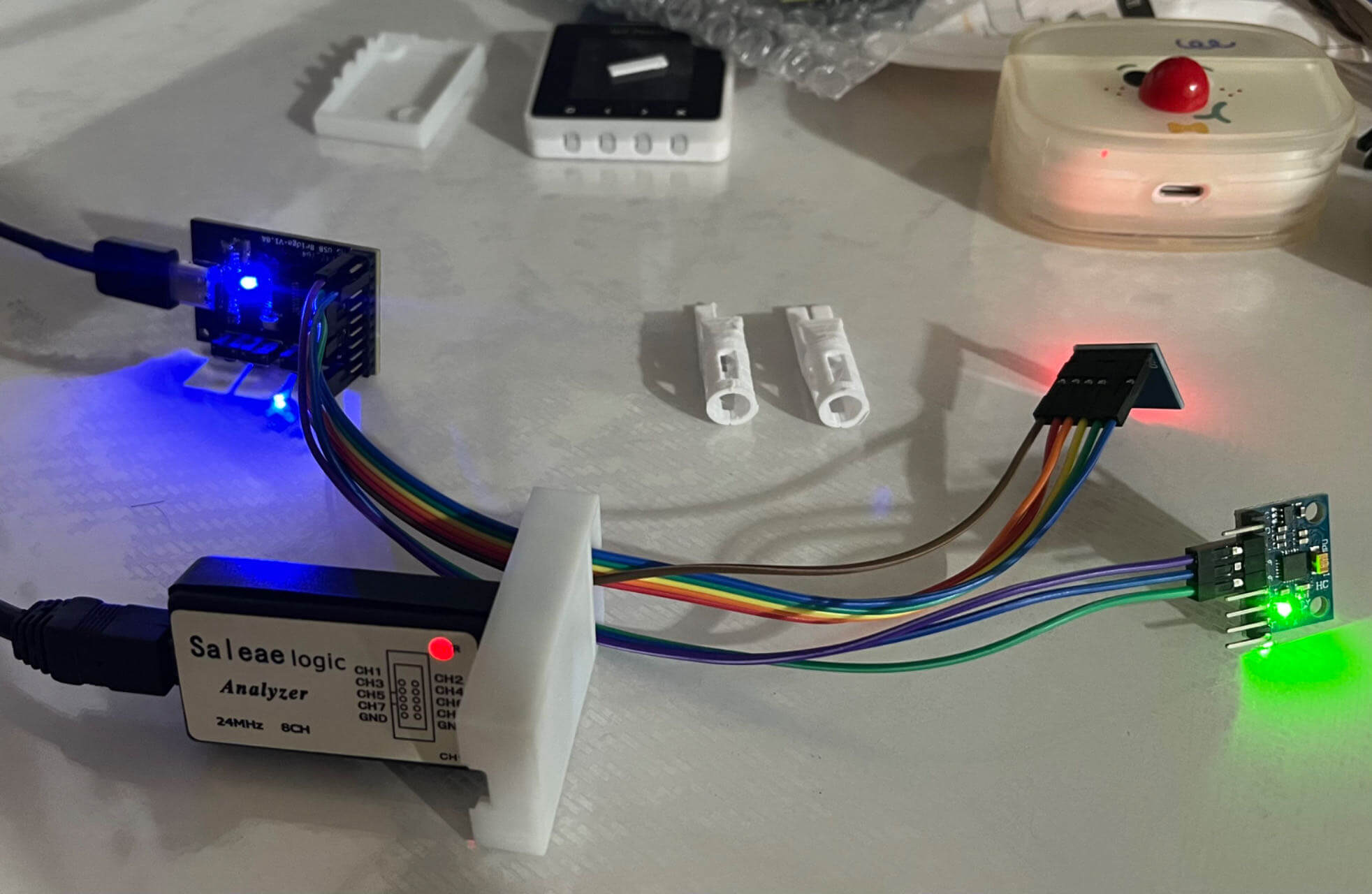
上图中,红色LED的是W25Q32FV SPI Flash模块,绿色LED的是MPU6050。
编写测试代码:
import ch347

dll_path = "ch347dlla64.dll"  # Replace with the actual path to the DLL
device_index = 0  # Set the device index according to your requirements

ch347_driver = ch347.CH347Driver(dll_path)

result = ch347_driver.open_device(device_index)
if result:
    print(f"Successfully opened device index: {device_index}")
else:
    print(f"Failed to close device index: {device_index}")

spi_config = ch347.SPIConfig(
    iMode = 0,
    iClock = 0,
    iByteOrder = 1,
    iSpiWriteReadInterval = 0,
    iSpiOutDefaultData = 0,
    iChipSelect = 0x80,
    CS1Polarity = 0,
    CS2Polarity = 0,
    iIsAutoDeative = 1,
    iActiveDelay = 0,
    iDelayDeactive = 0
)
result = ch347_driver.spi_init(device_index, spi_config)
if result:
    print("Success to init SPI.")
else:
    print("Failed to init SPI.")

# 读制造商数据
read_data = ch347_driver.spi_read(device_index, 0x80, b"\x90\x00\x00\x00", 2)
print(read_data)

# 读 0x000000 4个字节
read_data = ch347_driver.spi_read(device_index, 0x80, b"\x03\x00\x00\x00", 4)
print(read_data)

# 写 0x000000 2个字节 0x01 0x02
ch347_driver.spi_write(device_index, 0x80, b'\x06')
ch347_driver.spi_write(device_index, 0x80, b'\x02\x00\x00\x00\x01\x02')

# 读 0x000000 4个字节
read_data = ch347_driver.spi_read(device_index, 0x80, b"\x03\x00\x00\x00", 4)
print(read_data)

# Example usage of CH347CloseDevice
result = ch347_driver.close_device(device_index)
if result:
    print(f"Successfully closed device index: {device_index}")
else:
    print(f"Failed to close device index: {device_index}")
运行一下:
❯ python testSPI.py
Successfully opened device index: 0
Success to init SPI.
b'\xef\x15'
b'\xff\xff\xff\xff'
b'\x01\x02\xff\xff'
Successfully closed device index: 0
至此就可以读写SPI Flash了。
公众号 | FunIO
微信搜一搜 “funio”,发现更多精彩内容。
个人博客 | blog.boringhex.top