ZYNQ有两个CPU?(一)——AMP搭建
当初Xilinx技术支持忽悠我用ZYNQ的时候这双核就是其中一条广告词,可回想起来在Standalone下面我还真没好好用过双核所以在这里跟大家分享一下在Standalone下面如何搭建AMP分几个阶段进行,从最简单的做起。
至于什么是AMP和SMP我找了个链接就不做解释了:
多核处理器基础SMP&&BMP - zamely - 博客园
今天要做的事情是先在两个CPU上跑出两个完全并行的程序,相互之间没有交集。然后在把程序下载到Flash中让CPU0唤醒CPU1实现真正的AMP。在这个过程中我们还会分析和解决遇到的问题。
当然做事情之前得查资料,搜索一下文档浏览器以后找到了两篇XAPP1078和XAPP1079:一篇是双裸机,一篇是裸机+Linux。根据需求我选了后者,进去之后就发现自己被坑了。这篇文章是在ISE+XPS的古老环境中实现的,而我自己用的是VIVADO,这就悲剧了!
不过我还是把文档和参考设计down下来了。

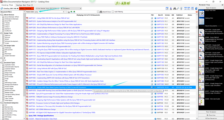
在文档中心用AMP做关键字搜到的XAPP1079


接下来是到Xilinx官网下载资料


下载后解压毕竟C代码还是有参考价值的。文档只有32页,跳过ISE和XPS的部分直接看SDK的内容。
看完后我就自己关注的内容总结了一下:
hw_platform不需要对AMP进行设置,主要工作都在SDK上。

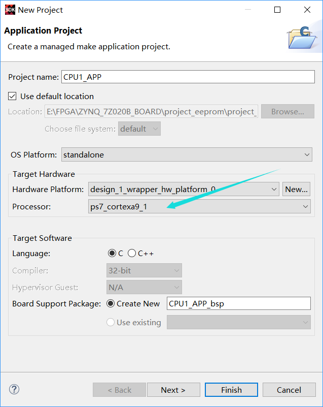
需要分别建立两个CPU的APP项目,其中CPU1的向导中要注意处理器选项选择CPU1。


CPU1的BSP SETTING需增加-DUSE_AMP=1。
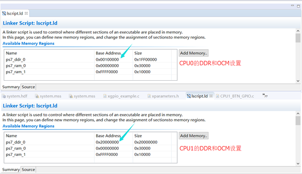

每个CPU的APP项目的src目录中按照自己预想的存储器分配方案修改lscript.ld文件中的内容,千万注意不要让两个CPU的DDR地址重合,因为你APP的ELF文件是加载到DDR中执行的。由于没有OS,ELF肯定是加载到每个CPU的DDR起始地址。如果有重合那么一个CPU的ELF会覆盖另一个的,别问我是怎么知道的。

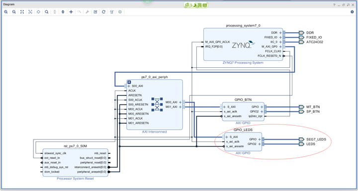
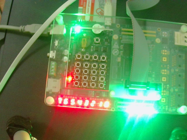
我在VIVADO中把开发板上的8位LED灯和七段数码管的24位驱动引脚做到了一个axi_gpio的两个通道上。在两个CPU上分别访问一个通道。

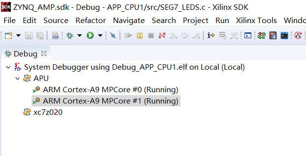
写完两个CPU的APP后,分别debug在各自的CPU上run起来,结果如下图:

然后当我把这个设计固化到flash里后发现只有CPU0跑起来了,为啥啊?这才想起自己down下来的代码,对比代码又查询了UG585才知道原因:即使fsbl已经把CPU1的ELF加载到位,但CPU1是处于waiting状态的。需要CPU发出WFE指令才能唤醒CPU1。而CPU1被唤醒后首先就是从地址0XFFFFFFF0读取地址进行跳转。因此CPU0在发出WFE指令前要在0XFFFFFFF0存入CPU1的DDR起始地址。而0XFFFFFFF0属于OCM的地址范围,所以需要去掉OCM这块儿的Cache属性。下面的代码需要包含库文件"xil_io.h"。
    //Disable cache on OCM
    Xil_SetTlbAttributes(0xFFFF0000,0x14de2);           // S=b1 TEX=b100 AP=b11, Domain=b1111, C=b0, B=b0
    Xil_Out32(CPU1_START_UP_REG, CPU1STARTADR); //CPU1STARTADR=0xFFFFFFF0, CPU1STARTADR=0x20000000);
    dmb(); //waits until write has finished
    print("CPU0: sending the SEV to wake up CPU1\n\r");
    __asm__("sev");
    dmb(); //waits until write has finished
修改完成烧写flash成功,运行成功。这是我LED.c的源代码
/***************************** Include Files *********************************/ #include "xparameters.h" #include "xgpio.h" #include "xil_printf.h" #include "xil_io.h" /************************** Constant Definitions *****************************/ #define LED 0x01 /* Assumes bit 0 of GPIO is connected to an LED */ /* * The following constants map to the XPAR parameters created in the * xparameters.h file. They are defined here such that a user can easily * change all the needed parameters in one place. */ #define GPIO_EXAMPLE_DEVICE_ID XPAR_GPIO_LEDS_DEVICE_ID /* * The following constant is used to wait after an LED is turned on to make * sure that it is visible to the human eye. This constant might need to be * tuned for faster or slower processor speeds. */ #define LED_DELAY 10000000 /* * The following constant is used to determine which channel of the GPIO is * used for the LED if there are 2 channels supported. */ #define LED_CHANNEL 2 #define CPU1_START_UP_REG 0xFFFFFFF0 #define CPU1STARTADR 0x20000000 /************************** Variable Definitions *****************************/ /* * The following are declared globally so they are zeroed and so they are * easily accessible from a debugger */ XGpio Gpio; /* The Instance of the GPIO Driver */ /*****************************************************************************/ /** * * The purpose of this function is to illustrate how to use the GPIO * driver to turn on and off an LED. * * @param None * * @return XST_FAILURE to indicate that the GPIO Initialization had * failed. * * @note This function will not return if the test is running. * ******************************************************************************/ int main(void) { int Status; volatile int Delay; int i; //Disable cache on OCM Xil_SetTlbAttributes(0xFFFF0000,0x14de2); // S=b1 TEX=b100 AP=b11, Domain=b1111, C=b0, B=b0 Xil_Out32(CPU1_START_UP_REG, CPU1STARTADR); //CPU1STARTADR=0xFFFFFFF0, CPU1STARTADR=0x20000000); dmb(); //waits until write has finished print("CPU0: sending the SEV to wake up CPU1\n\r"); __asm__("sev"); dmb(); //waits until write has finished xil_printf("Start to light the leds\r\n"); /* Initialize the GPIO driver */ Status = XGpio_Initialize(&Gpio, GPIO_EXAMPLE_DEVICE_ID); if (Status != XST_SUCCESS) { xil_printf("Gpio Initialization Failed\r\n"); return XST_FAILURE; } /* Set the direction for all signals as inputs except the LED output */ XGpio_SetDataDirection(&Gpio, LED_CHANNEL, 0);//set all pins as output /* Loop forever blinking the LED */ while (1) { for (i=0;i<8;i++) { /* Set one LED light each time */ XGpio_DiscreteWrite(&Gpio, LED_CHANNEL, ~(LED<<i));<span class="cm">/* Wait a small amount of time so the LED is visible */</span> <span class="k">for</span> <span class="p">(</span><span class="n">Delay</span> <span class="o">=</span> <span class="mi">0</span><span class="p">;</span> <span class="n">Delay</span> <span class="o"><</span> <span class="n">LED_DELAY</span><span class="p">;</span> <span class="n">Delay</span><span class="o">++</span><span class="p">);</span> <span class="p">}</span> <span class="p">}</span> <span class="c1">//xil_printf("Successfully ran Gpio Example\r\n");