基础配置
- 使用单片机APM32F103RBT6
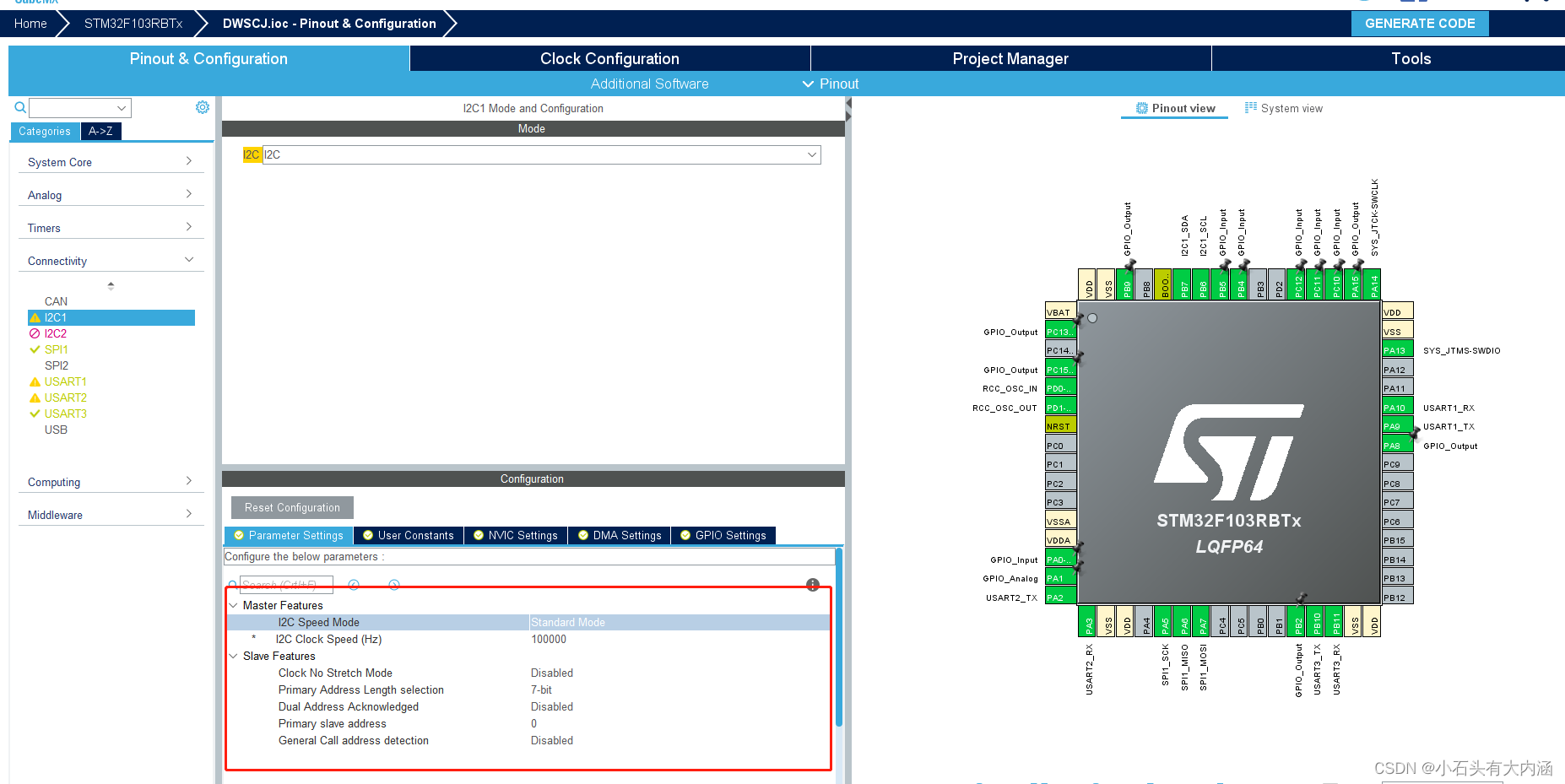
- 使用外设I2C1 - PB7 SDA
- 使用外设I2C1 - PB6 SCK
- STM32CUBEMX 版本5.6
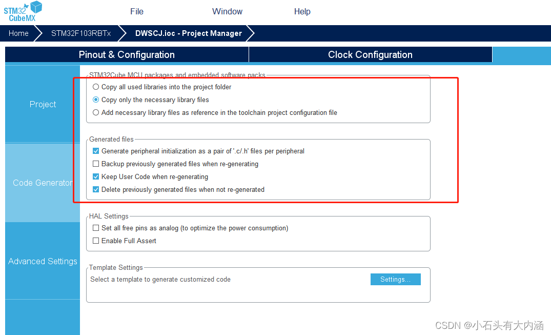
配置如下
i2c.c文件
/**
******************************************************************************
* File Name : I2C.c
* Description : This file provides code for the configuration
* of the I2C instances.
******************************************************************************
* @attention
*
* <h2><center>© Copyright (c) 2022 STMicroelectronics.
* All rights reserved.</center></h2>
*
* This software component is licensed by ST under Ultimate Liberty license
* SLA0044, the "License"; You may not use this file except in compliance with
* the License. You may obtain a copy of the License at:
* www.st.com/SLA0044
*
******************************************************************************
*/
/* Includes ------------------------------------------------------------------*/
#include "i2c.h"
/* USER CODE BEGIN 0 */
/* USER CODE END 0 */
I2C_HandleTypeDef hi2c1;
/* I2C1 init function */
void MX_I2C1_Init(void)
{
hi2c1.Instance = I2C1;
hi2c1.Init.ClockSpeed = 100000;
hi2c1.Init.DutyCycle = I2C_DUTYCYCLE_2;
hi2c1.Init.OwnAddress1 = 0;
hi2c1.Init.AddressingMode = I2C_ADDRESSINGMODE_7BIT;
hi2c1.Init.DualAddressMode = I2C_DUALADDRESS_DISABLE;
hi2c1.Init.OwnAddress2 = 0;
hi2c1.Init.GeneralCallMode = I2C_GENERALCALL_DISABLE;
hi2c1.Init.NoStretchMode = I2C_NOSTRETCH_DISABLE;
if (HAL_I2C_Init(&hi2c1) != HAL_OK)
{
Error_Handler();
}
}
void HAL_I2C_MspInit(I2C_HandleTypeDef* i2cHandle)
{
GPIO_InitTypeDef GPIO_InitStruct = {0};
if(i2cHandle->Instance==I2C1)
{
/* USER CODE BEGIN I2C1_MspInit 0 */
/* USER CODE END I2C1_MspInit 0 */
__HAL_RCC_GPIOB_CLK_ENABLE();
/**I2C1 GPIO Configuration
PB6 ------> I2C1_SCL
PB7 ------> I2C1_SDA
*/
GPIO_InitStruct.Pin = GPIO_PIN_6|GPIO_PIN_7;
GPIO_InitStruct.Mode = GPIO_MODE_AF_OD;
GPIO_InitStruct.Speed = GPIO_SPEED_FREQ_HIGH;
HAL_GPIO_Init(GPIOB, &GPIO_InitStruct);
/* I2C1 clock enable */
__HAL_RCC_I2C1_CLK_ENABLE();
/* USER CODE BEGIN I2C1_MspInit 1 */
/* USER CODE END I2C1_MspInit 1 */
}
}
void HAL_I2C_MspDeInit(I2C_HandleTypeDef* i2cHandle)
{
if(i2cHandle->Instance==I2C1)
{
/* USER CODE BEGIN I2C1_MspDeInit 0 */
/* USER CODE END I2C1_MspDeInit 0 */
/* Peripheral clock disable */
__HAL_RCC_I2C1_CLK_DISABLE();
/**I2C1 GPIO Configuration
PB6 ------> I2C1_SCL
PB7 ------> I2C1_SDA
*/
HAL_GPIO_DeInit(GPIOB, GPIO_PIN_6|GPIO_PIN_7);
/* USER CODE BEGIN I2C1_MspDeInit 1 */
/* USER CODE END I2C1_MspDeInit 1 */
}
}
/* USER CODE BEGIN 1 */
/*******************************************************************************
* 函数名: WriteI2CTData
* 描述 : 写入I2C数据
* 参数 : addr设备地址,reg 寄存器地址 *buf写入的数据,len写入的长度
* 返回值:
*******************************************************************************/
HAL_StatusTypeDef WriteI2cData(uint8_t addr, uint8_t reg, uint8_t *pBuffer, uint8_t len)
{
HAL_StatusTypeDef status = HAL_OK;
status = HAL_I2C_Mem_Write(&hi2c1, addr, (uint16_t)reg, I2C_MEMADD_SIZE_8BIT, pBuffer, len, 1000);
return status;
}
/*******************************************************************************
* 函数名: ReadI2cData
* 描述 : 读RX8025T寄存器
* 参数 : addr寄存器地址,*buf存储位置,len读取的长度
* 返回值: 1=操作失败,0=操作成功
*******************************************************************************/
uint8_t ReadI2cData(uint8_t addr, uint8_t reg, uint8_t *buf,uint8_t len)
{
HAL_StatusTypeDef status = HAL_OK;
status = HAL_I2C_Mem_Read(&hi2c1, addr, (uint16_t)reg, I2C_MEMADD_SIZE_8BIT, buf, len, 1000);
return status;
}
/*******************************************************************************
* 函数名: I2cIsDeviceReady
* 描述 : 检测I2C设备是否处于准备好可以通信状态
* 参数 : DevAddress 设备地址,Trials 尝试测试次数
* 返回值:
*******************************************************************************/
HAL_StatusTypeDef I2cIsDeviceReady(uint16_t DevAddress, uint32_t Trials)
{
return (HAL_I2C_IsDeviceReady(&hi2c1, DevAddress, Trials, 1000));
}
/* USER CODE END 1 */
/************************ (C) COPYRIGHT STMicroelectronics *****END OF FILE****/
i2c.h文件
/**
******************************************************************************
* File Name : I2C.h
* Description : This file provides code for the configuration
* of the I2C instances.
******************************************************************************
* @attention
*
* <h2><center>© Copyright (c) 2022 STMicroelectronics.
* All rights reserved.</center></h2>
*
* This software component is licensed by ST under Ultimate Liberty license
* SLA0044, the "License"; You may not use this file except in compliance with
* the License. You may obtain a copy of the License at:
* www.st.com/SLA0044
*
******************************************************************************
*/
/* Define to prevent recursive inclusion -------------------------------------*/
#ifndef __i2c_H
#define __i2c_H
#ifdef __cplusplus
extern "C" {
#endif
/* Includes ------------------------------------------------------------------*/
#include "main.h"
/* USER CODE BEGIN Includes */
/* USER CODE END Includes */
extern I2C_HandleTypeDef hi2c1;
/* USER CODE BEGIN Private defines */
/* USER CODE END Private defines */
void MX_I2C1_Init(void);
/* USER CODE BEGIN Prototypes */
HAL_StatusTypeDef WriteI2cData(uint8_t addr, uint8_t reg, uint8_t *pBuffer, uint8_t len);
uint8_t ReadI2cData(uint8_t addr, uint8_t reg, uint8_t *buf,uint8_t len);
HAL_StatusTypeDef I2cIsDeviceReady(uint16_t DevAddress, uint32_t Trials);
/* USER CODE END Prototypes */
#ifdef __cplusplus
}
#endif
#endif /*__ i2c_H */
/**
* @}
*/
/**
* @}
*/
/************************ (C) COPYRIGHT STMicroelectronics *****END OF FILE****/
bsp_rtc.c文件(名字可以自己随意定义)
#include "bsp.h"
#include "app_task.h"


#define  RX8025T_DEVICE_ADDRESS  0x64


/***********************************************************************************

		RX8025T实时时钟驱动程序(硬件IIC)

		BL8025T 的从地址为 7bit 固定的数据(0110 010)在通信时,从地址是附加上 R/W 以 8bit 数据发送的。
		0110 0100为写模式,0110 0101为读模式,对应十进制为:100、101;对应16进制为:0x64、0x65。

		BL8025T 有地址自动增加功能。指定的从地址一旦开始,之后只有数据字节被发送。每个字节后,BL8025T 的地址自动增加。

***********************************************************************************/


/*
*********************************************************************************************************
*	函 数 名: bsp_InitRtc
*	功能说明: 初始RTC. 该函数被 bsp_Init() 调用。
*	形    参: 无
*	返 回 值: 无
*********************************************************************************************************
*/
void bsp_InitRtc(void)
{

	uint8_t status;
		//固定周期时钟源为分钟更新
	uint8_t val[3]={0x03,0x00,0x40};  //0x0D、0x0E、0x0F、三个寄存器的值,设置时间更新为“秒”更新,关闭所有闹钟,温补时间为2秒,打开时间更新中断,关闭其他中断。


	status = WriteI2cData(RX8025T_DEVICE_ADDRESS, RX8025T_EXT_REG,val,3);

  printf("RX8025T set OK! %d\r\n", status);
}


/*******************************************************************************
* 函数名: bsp_SetRTCAlarm
* 描述  : 设置RX8025T的闹钟
* 参数  : 存储时间的结构体
* 返回值: 0成功,其它失败。
*******************************************************************************/
uint8_t bsp_SetRTCAlarm(uint16_t alarm)
{
	 	uint8_t  status;
		uint8_t  value = 0;
		uint8_t  reg_cy1[2];//报警固定周期寄存器
		uint8_t  reg[3];
//	uint8_t  buf[5];
/*
		固定周期定时器配置

		先将TIE置“0”,以避免在配置固定周期中断的同时发生意外的硬件中断。
		(1) 设定TSEL1,0两位选择倒计时周期。
		(2) 设定B,C寄存器,从而设置减法计数器的初值,然后初始化TF标志为“0”。
		(3) 设置TIE,TE位为“1”

*/
			value = 0x40;
			status = WriteI2cData(RX8025T_DEVICE_ADDRESS, RX8025T_CONT_REG, &value, 1);

			value = 0x00;
			status = WriteI2cData(RX8025T_DEVICE_ADDRESS, RX8025T_EXT_REG, &value, 1);

			reg_cy1[0] = alarm & 0xFF;
			reg_cy1[1] = (alarm >> 8) & 0xFF;
			status = WriteI2cData(RX8025T_DEVICE_ADDRESS, RX8025T_CYl_REG, reg_cy1, 2);

			reg[0] = 0x13;		//分钟更新
			reg[1] = 0x10;
			reg[2] = 0x50;
			status = WriteI2cData(RX8025T_DEVICE_ADDRESS, RX8025T_EXT_REG, reg, 3);

			return status;

}

/*******************************************************************************
* 函数名: bsp_GetRtcTime
* 描述  : 从RX8025T获取时间
* 参数  : 存储时间的结构体
* 返回值: 0成功,1失败。
*******************************************************************************/
uint8_t bsp_GetRtcTime(TIME_T *t)
{
	uint8_t rtc_str[7];

	if(ReadI2cData(RX8025T_DEVICE_ADDRESS, RX8025T_SEC_REG, rtc_str,7) != 0)  //获取日期与时间
		return 1;  //读取出错

	t->second = ((rtc_str[0]>>4)*10) + (rtc_str[0] & 0x0f);
	t->minute = ((rtc_str[1]>>4)*10) + (rtc_str[1] & 0x0f);
	t->hour   = ((rtc_str[2]>>4)*10) + (rtc_str[2] & 0x0f);
	t->week		= rtc_str[3];
	t->day    = ((rtc_str[4]>>4)*10) + (rtc_str[4] & 0x0f);
	t->month  = ((rtc_str[5]>>4)*10) + (rtc_str[5] & 0x0f);
  t->year   = ((rtc_str[6]>>4)*10) + (rtc_str[6] & 0x0f);

	return 0;
}

/*******************************************************************************
* 函数名: bsp_SetRtcTime
* 描述  : 设置RX8025T时间
* 参数  : 存储时间的结构体
* 返回值: 0成功,1失败。
*******************************************************************************/
uint8_t bsp_SetRtcTime(TIME_T *t)
{
		uint8_t  status;
		uint8_t rtc_str[7];

		rtc_str[0] = ((t->second/10)<<4) | (t->second%10);
		rtc_str[1] = ((t->minute/10)<<4) | (t->minute%10);
		rtc_str[2] = ((t->hour/10)<<4) | (t->hour%10);
		rtc_str[3] = t->week;
		rtc_str[4] = ((t->day/10)<<4) | (t->day%10);
		rtc_str[5] = ((t->month/10)<<4) | (t->month%10);
		rtc_str[6] = ((t->year/10)<<4) | (t->year%10);


		status = WriteI2cData(RX8025T_DEVICE_ADDRESS, RX8025T_SEC_REG, rtc_str, 7);
		return status;
}
bsp_rtc.h文件(名字可以自己随意定义)
#ifndef _BSP_RTC_H_
#define _BSP_RTC_H_


#define RX8025T_SEC_REG		0x00	//秒
#define RX8025T_MIN_REG 	0x01	//分
#define RX8025T_HOU_REG		0x02	//时
#define RX8025T_WEE_REG	  0x03	//星期,bit0~bit7对应日、一、二、三、四、五、六,对应值为0x01,0x02,0x04,0x08,0x10,0x20,0x40,不可出现2位为1的情况。
#define RX8025T_DAY_REG		0x04	//日期
#define RX8025T_MON_REG 	0x05	//月份
#define RX8025T_YEA_REG		0x06	//年
#define RX8025T_RAM_REG		0x07	//RAM

#define RX8025T_ALm_REG 	0x08	//闹钟分,不用是可做为ram使用。
#define RX8025T_ALh_REG		0x09	//闹钟时,不用是可做为ram使用。

#define RX8025T_ALw_REG 	0x0a	//闹钟星期,不用是可做为ram使用。
#define RX8025T_CYl_REG	  0x0b	//周期定时器的低8位
#define RX8025T_CYm_REG	  0x0c	//周期定时器的高4位,周期定时器共计12位。

#define RX8025T_EXT_REG	  0x0d	//扩展寄存器,bit7-TEST=工厂测试,总应该写0;bit6-WADA=星期或日历报警选择位;bit5-USEL=选择秒或分钟更新触发更新中断,0=秒更新,1=分钟更新;
																		        //bit4-TE=周期定时使能;bit3\2-FSEL1\0=芯片FOUT引脚输出频率选择位;bit1\0-TSEL1\0=用来设定固定周期的内部时钟源。

#define RX8025T_FLAG_REG	0x0e	//标志寄存器,bit5-UF,bit4-TF,bit3-AF,分别是时间更新中断,固定周期定时中断,闹钟中断的中断标志位;bit1-VLF电压低,bit0-VDET由于电压低温补停止工作标志位。

#define RX8025T_CONT_REG 	0x0f	//控制寄存器,bit6~7(CSEL0、1)=温补间隔设置;bit5(UIE)=时间更新中断使能位(可由D寄存器的USEL位配置为1秒更新或1分钟更新);


#define TESL1_0_CLOCK_4069			0
#define TESL1_0_CLOCK_64				1
#define TESL1_0_CLOCK_S					2
#define TESL1_0_CLOCK_M					3


//TE 位  此位是用来控制固定周期定时功能使能。
//置“1”是选择开启固定周期定时功能。
//置“0”是选择关闭固定周期定时功能。
#define TE_1											1<<4
#define TE_0											(~(1<<4))


#define TF_1											1<<4
#define TF_0											(~(1<<4))


#define TF_FLAG										0x10


//定时中断使能位
#define TIE_1											1<<4
#define TIE_0											(~(1<<4))


typedef struct  // _TIME
{
	uint8_t second;
	uint8_t minute;
	uint8_t hour;
	uint8_t week;
	uint8_t day;
	uint8_t month;
	uint8_t year;
	uint8_t reserve;
}TIME_T;


void bsp_InitRtc(void);
uint8_t bsp_SetRTCAlarm(uint16_t alarm);
uint8_t bsp_SetRtcTime(TIME_T *t);
uint8_t bsp_GetRtcTime(TIME_T *t);


#endif