1. 资源简介
- stm32 rct6板
- SG90舵机模块
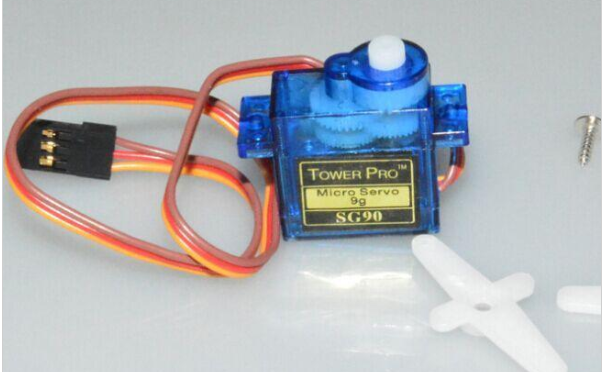
接线引脚:
橙色:信号线
红色:电源+5v
咖色:GND
此模块三条线固定在一起,如果用开发板测试需要连线的情况下需要一公一母的杜邦线转接一下才行
2.测试源码
不需要其它的文件,测试用只需要将下面代码全部复制到main函数编译运行即可:
#include "stm32f10x.h"
void pwm_init(void);
void delay(uint32_t x);
int main()
{
pwm_init();
while(1)
{
TIM_SetCompare1(TIM3, 195);
delay(10000000);
TIM_SetCompare1(TIM3, 185);
delay(10000000);
}
}
void pwm_init()
{
GPIO_InitTypeDef GPIO_InitStructure;
TIM_TimeBaseInitTypeDef TIM_TimeBaseInitStructure;
TIM_OCInitTypeDef TIM_OCInitStructure;
RCC_APB2PeriphClockCmd(RCC_APB2Periph_GPIOC,ENABLE);
RCC_APB1PeriphClockCmd(RCC_APB1Periph_TIM3,ENABLE);
RCC_APB2PeriphClockCmd(RCC_APB2Periph_AFIO,ENABLE);
GPIO_InitStructure.GPIO_Pin=GPIO_Pin_6;
GPIO_InitStructure.GPIO_Speed=GPIO_Speed_50MHz;
GPIO_InitStructure.GPIO_Mode=GPIO_Mode_AF_PP;
GPIO_Init(GPIOC,&GPIO_InitStructure);
TIM_TimeBaseInitStructure.TIM_Period = 199;
TIM_TimeBaseInitStructure.TIM_Prescaler = 7199;
TIM_TimeBaseInitStructure.TIM_ClockDivision = 0;
TIM_TimeBaseInitStructure.TIM_CounterMode = TIM_CounterMode_Up;
TIM_TimeBaseInit(TIM3, & TIM_TimeBaseInitStructure);
GPIO_PinRemapConfig(GPIO_FullRemap_TIM3,ENABLE);
TIM_OCInitStructure.TIM_OCMode=TIM_OCMode_PWM1;
TIM_OCInitStructure.TIM_OutputState=TIM_OutputState_Enable;
TIM_OCInitStructure.TIM_OCPolarity=TIM_OCPolarity_Low;
TIM_OC1Init(TIM3,&TIM_OCInitStructure);
TIM_OC1PreloadConfig(TIM3, TIM_OCPreload_Enable);
TIM_Cmd(TIM3,ENABLE);
}
void delay(uint32_t x)
{
while(x--);
}
本文内容由网友自发贡献,版权归原作者所有,本站不承担相应法律责任。如您发现有涉嫌抄袭侵权的内容,请联系:hwhale#tublm.com(使用前将#替换为@)