SmartLink CC265x是TI公司出的无线MCU平台器件。最近玩了个小项目用TI的CC265x平板IIC接口通讯,获取博世BMI08x陀螺仪、加速度计传感器的数据。本篇博客亦是对博客《树莓派IIC通讯获取BMI08x IMU数据进行姿态解算,并通过UART/TCP在rviz上显示》的一个扩展。
目录
1. CCS(Code Composer Studio)的安装
2. IIC模块的配置与调试
1. CCS(Code Composer Studio)的安装
CCS的针对TI开发板的编程与下载工具,最新软件可在CCSTUDIO IDE、配置、编译器或调试器 | TI.com.cn下载,其使用手册可以在Code Composer Studio User’s Guide — Code Composer Studio 11.0.0 Documentation中查看。
大多数情况下我们是使用安装好之后的官方自带例程,并再其基础上更新。
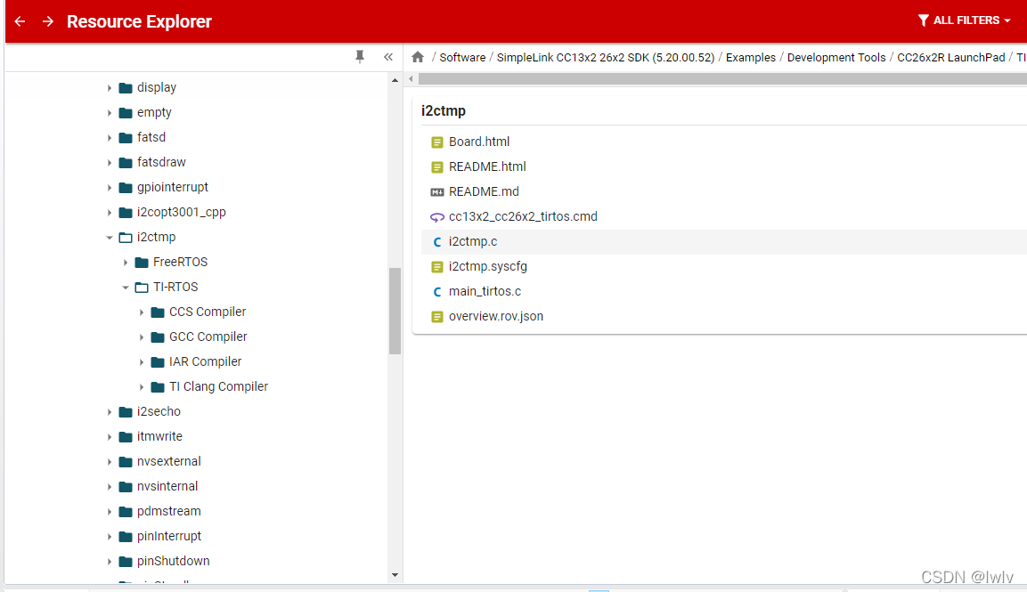
比如我们想要了解I2C相关的例程,直接选择后import导入到本地路径。
关于如何从零建立自己的CCS工程,暂时还没研究清楚,有大神清楚还望多多指教,万分感谢。
2. IIC模块的配置与调试
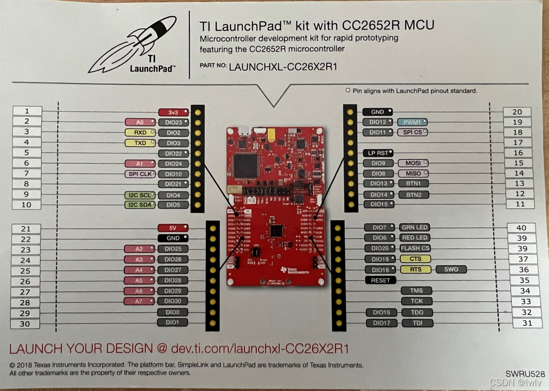
我开发的TI板是CC2652,9,10号引脚为I2C的通讯线。
这些引脚的定义需结合syscfg,比如Display表示可通过开发板的串口将数据打印出来,TI的库已经封装好了这一层。
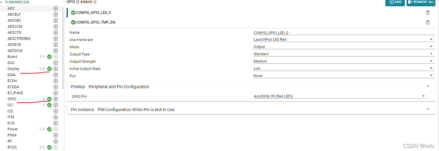
另外还可以配置一些GPIO用于LED灯的操作。
官方的给的IIC例程写得有点让人难理解,全都封装在I2C_Transaction函数了,在读寄存器处并没有说明要写入寄存器地址。
* // Import I2C Driver definitions
* #include <ti/drivers/I2C.h>
*
* // Define name for an index of an I2C bus
* #define SENSORS 0
*
* // Define the slave address of device on the SENSORS bus
* #define OPT_ADDR 0x47
*
* // One-time init of I2C driver
* I2C_init();
*
* // initialize optional I2C bus parameters
* I2C_Params params;
* I2C_Params_init(¶ms);
* params.bitRate = I2C_400kHz;
*
* // Open I2C bus for usage
* I2C_Handle i2cHandle = I2C_open(SENSORS, ¶ms);
*
* // Initialize slave address of transaction
* I2C_Transaction transaction = {0};
* transaction.slaveAddress = OPT_ADDR;
*
* // Read from I2C slave device
* transaction.readBuf = data;
* transaction.readCount = sizeof(data);
* transaction.writeCount = 0;
* I2C_transfer(i2cHandle, &transaction);
*
* // Write to I2C slave device
* transaction.writeBuf = command;
* transaction.writeCount = sizeof(command);
* transaction.readCount = 0;
* I2C_transferTimeout(i2cHandle, &transaction, 5000);
*
* // Close I2C
* I2C_close(i2cHandle);
* @endcode
*
* @anchor ti_drivers_I2C_Examples
* ## Examples
*
* @li @ref ti_drivers_I2C_Example_open "Getting an I2C bus handle"
* @li @ref ti_drivers_I2C_Example_write3bytes "Sending 3 bytes"
* @li @ref ti_drivers_I2C_Example_read5bytes "Reading 5 bytes"
* @li @ref ti_drivers_I2C_Example_writeread "Writing then reading in a single transaction"
* @li @ref ti_drivers_I2C_Example_callback "Using Callback mode"
*
* @anchor ti_drivers_I2C_Example_open
* ## Opening the I2C Driver
*
* After calling I2C_init(), the application can open an I2C instance by
* calling I2C_open().The following code example opens an I2C instance with
* default parameters by passing @p NULL for the #I2C_Params argument.
*
* @code
* I2C_Handle i2cHandle;
*
* i2cHandle = I2C_open(0, NULL);
*
* if (i2cHandle == NULL) {
* // Error opening I2C
* while (1) {}
* }
* @endcode
*
* @anchor ti_drivers_I2C_Example_write3bytes
* ## Sending three bytes of data.
*
* @code
* I2C_Transaction i2cTransaction = {0};
* uint8_t writeBuffer[3];
*
* writeBuffer[0] = 0xAB;
* writeBuffer[1] = 0xCD;
* writeBuffer[2] = 0xEF;
*
* i2cTransaction.slaveAddress = 0x50;
* i2cTransaction.writeBuf = writeBuffer;
* i2cTransaction.writeCount = 3;
* i2cTransaction.readBuf = NULL;
* i2cTransaction.readCount = 0;
*
* status = I2C_transfer(i2cHandle, &i2cTransaction);
*
* if (status == false) {
* // Unsuccessful I2C transfer
* if (i2cTransaction.status == I2C_STATUS_ADDR_NACK) {
* // I2C slave address not acknowledged
* }
* }
* @endcode
*
* @anchor ti_drivers_I2C_Example_read5bytes
* ## Reading five bytes of data.
*
* @code
* I2C_Transaction i2cTransaction = {0};
* uint8_t readBuffer[5];
*
* i2cTransaction.slaveAddress = 0x50;
* i2cTransaction.writeBuf = NULL;
* i2cTransaction.writeCount = 0;
* i2cTransaction.readBuf = readBuffer;
* i2cTransaction.readCount = 5;
*
* status = I2C_transfer(i2cHandle, &i2cTransaction);
*
* if (status == false) {
* if (i2cTransaction.status == I2C_STATUS_ADDR_NACK) {
* // I2C slave address not acknowledged
* }
* }
* @endcode
*
* @anchor ti_drivers_I2C_Example_writeread
* ## Writing two bytes and reading four bytes in a single transaction.
*
* @code
* I2C_Transaction i2cTransaction = {0};
* uint8_t readBuffer[4];
* uint8_t writeBuffer[2];
*
* writeBuffer[0] = 0xAB;
* writeBuffer[1] = 0xCD;
*
* i2cTransaction.slaveAddress = 0x50;
* i2cTransaction.writeBuf = writeBuffer;
* i2cTransaction.writeCount = 2;
* i2cTransaction.readBuf = readBuffer;
* i2cTransaction.readCount = 4;
*
* status = I2C_transfer(i2cHandle, &i2cTransaction);
*
* if (status == false) {
* if (i2cTransaction->status == I2C_STATUS_ADDR_NACK) {
* // slave address not acknowledged
* }
* }
* @endcode
感谢 获夜 的博文《CC2652RB硬件I2C读取FXOS8700CQ加速度传感器》 及其给与的帮助,让我对TI CCS使用IIC库有所理解。这里依旧使用博世官方提供的API “https://github.com/BoschSensortec/BMI08x-Sensor-API”,对common函数的读写操作进行了改进(而不是使用博世提供的COINES平台)。
更改为TI获取IIC的读写寄存器操作如下:
/*!
* I2C read function map to SimpleLink launchpad
*/
int8_t bmi08x_i2c_read(uint8_t reg_addr, uint8_t *reg_data, uint32_t len, void *intf_ptr)
{
uint8_t dev_addr = *(uint8_t*)intf_ptr;
/* Common I2C transaction setup */
i2cTransaction.slaveAddress = dev_addr;
i2cTransaction.writeBuf = ®_addr;
i2cTransaction.writeCount = 1;
i2cTransaction.readBuf = reg_data;
i2cTransaction.readCount = len;
uint8_t cnt = 0;
if (I2C_transfer(i2c_handle, &i2cTransaction)) {
for(cnt = 0; cnt < len; cnt++)
Display_printf(display, 0, 0, "Device 0x%x read register 0x%x value = 0x%x", dev_addr, reg_addr+cnt, reg_data[cnt]);
}
else {
i2cErrorHandler(&i2cTransaction, display);
return -2;
}
return 0;
}
/*!
* I2C write function map to SimpleLink launchpad
*/
int8_t bmi08x_i2c_write(uint8_t reg_addr, const uint8_t *reg_data, uint32_t len, void *intf_ptr)
{
uint8_t dev_addr = *(uint8_t*)intf_ptr;
i2cTransaction.slaveAddress = dev_addr;
uint8_t cnt = 0;
for(cnt = 0; cnt < len; cnt++)
{
uint8_t writeBuf[2] = {0};
writeBuf[0] = reg_addr+cnt;
writeBuf[1] = reg_data[cnt];
/* Common I2C transaction setup */
i2cTransaction.writeBuf = writeBuf;
i2cTransaction.writeCount = 2;
i2cTransaction.readBuf = NULL;
i2cTransaction.readCount = 0;
if (I2C_transfer(i2c_handle, &i2cTransaction)) {
Display_printf(display, 0, 0, "Device 0x%x write register 0x%x value = 0x%x", dev_addr, reg_addr + cnt, reg_data[cnt]);
}
else {
i2cErrorHandler(&i2cTransaction, display);
return -2;
}
}
return 0;
}
/*
* ======== i2cErrorHandler ========
*/
void i2cErrorHandler(I2C_Transaction *transaction, Display_Handle display)
{
switch (transaction->status) {
case I2C_STATUS_TIMEOUT:
Display_printf(display, 0, 0, "I2C transaction timed out!");
break;
case I2C_STATUS_CLOCK_TIMEOUT:
Display_printf(display, 0, 0, "I2C serial clock line timed out!");
break;
case I2C_STATUS_ADDR_NACK:
Display_printf(display, 0, 0, "I2C slave address 0x%x not"
" acknowledged!", transaction->slaveAddress);
break;
case I2C_STATUS_DATA_NACK:
Display_printf(display, 0, 0, "I2C data byte not acknowledged!");
break;
case I2C_STATUS_ARB_LOST:
Display_printf(display, 0, 0, "I2C arbitration to another master!");
break;
case I2C_STATUS_INCOMPLETE:
Display_printf(display, 0, 0, "I2C transaction returned before completion!");
break;
case I2C_STATUS_BUS_BUSY:
Display_printf(display, 0, 0, "I2C bus is already in use!");
break;
case I2C_STATUS_CANCEL:
Display_printf(display, 0, 0, "I2C transaction cancelled!");
break;
case I2C_STATUS_INVALID_TRANS:
Display_printf(display, 0, 0, "I2C transaction invalid!");
break;
case I2C_STATUS_ERROR:
Display_printf(display, 0, 0, "I2C generic error!");
break;
default:
Display_printf(display, 0, 0, "I2C undefined error case!");
break;
}
}
而这两个读写IIC寄存器恰好是获取IMU数据的关键。在IIC线程获取到数据后我们可以通过Display_printf函数将其打印出来。这样通过串口助手便将数据显示出来了,如下。
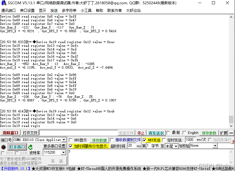
Enjoy!
本文内容由网友自发贡献,版权归原作者所有,本站不承担相应法律责任。如您发现有涉嫌抄袭侵权的内容,请联系:hwhale#tublm.com(使用前将#替换为@)