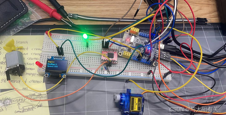
智能小家居------舵机开门,电机做风扇 or 拉窗帘、呼吸灯做提示,小OLED屏幕显示当前状态。
文章目录
- 直接上代码
- main.c
- pwm.h
- pwm.c
- servo.h
- servo.c
- motor.h
- motor.c
- 笔记仅供自学,用来回看复习,不一定适合你,如有错误请指出。
直接上代码
背景:我觉得我看了那么多教程了,然而只会玩单个东西,串起来就不太懂。
本项目的代码部分实现用到了2个时钟,TIM2 和 TIM3。
经历的问题:原本我是想只用一个时钟,不同通道来实现PWM的输出,但是我发现 我如果把TIM_TimeBaseInitStructure.TIM_Period = ARR ; //ARR 自动重装器的值
ARR = 20000 -1 时,只能驱动舵机,不能驱动电机。
ARR = 100 -1 时,只能驱动电机,不能驱动舵机。
后来发现: SG90舵机接收的PWM信号频率为50HZ,T=1/f,所以周期为20ms。 当高电平的脉宽在0.5ms-2.5ms之间时舵机就可以对应旋转到不同的角度。
解决方案:所以后来使用了2个时钟,分别输出上面这2个ARR的PWM。
明天准备再加一个呼吸灯功能。
如果你有更好的方案,可以留言或者私信我哦,我们可以交流交流哈哈哈,一起进步呀。
main.c
#include "stm32f10x.h"
#include "Delay.h"
#include "LED.h"
#include "Key.h"
#include "OLED.h"
#include "Servo.h"
#include "PWM.h"
#include "Motor.h"
extern void Motor_Set_Dir(int8_t Speed);
extern void Exti_Test_Pull_Level_Set(void);
uint8_t i,KeyNum;
int main(void)
{
Key_Init();
OLED_Init();
Servo_Init();
Motor_Init();
OLED_ShowString(1,1,"Angle:");
OLED_ShowString(2,1,"KeyNum:");
OLED_ShowString(3,1,"Speed:");
Servo_Set_Angle(0);
while (1)
{
KeyNum = Key_GetNum();
Servo_Turn(KeyNum);
Motor_Speed_Set(KeyNum);
}
}
pwm.h
#ifndef __PWM_H
#define __PWM_H
#include "stm32f10x.h"
void Servo_PWM_Init();
void Motor_PWM_Init();
void PWM_SetCompare_Servo(uint16_t Compare);
void PWM_SetCompare_Motor(uint16_t Compare);
#endif
pwm.c
#include "stm32f10x.h"
#define TIM2_CH2 GPIO_Pin_1
#define TIM3_CH1 GPIO_Pin_6
void Servo_PWM_Init()
{
GPIO_InitTypeDef GPIO_InitStructure;
TIM_TimeBaseInitTypeDef TIM_TimeBaseInitStructure;
TIM_OCInitTypeDef TIM_OCInitStructure;
RCC_APB1PeriphClockCmd(RCC_APB1Periph_TIM2,ENABLE);
RCC_APB2PeriphClockCmd(RCC_APB2Periph_GPIOA,ENABLE);
GPIO_InitStructure.GPIO_Mode = GPIO_Mode_AF_PP;
GPIO_InitStructure.GPIO_Pin = TIM2_CH2;
GPIO_InitStructure.GPIO_Speed = GPIO_Speed_50MHz;
GPIO_Init(GPIOA, &GPIO_InitStructure);
TIM_InternalClockConfig(TIM2);
TIM_TimeBaseInitStructure.TIM_ClockDivision = TIM_CKD_DIV1;
TIM_TimeBaseInitStructure.TIM_CounterMode = TIM_CounterMode_Up;
TIM_TimeBaseInitStructure.TIM_Period = 20000 - 1;
TIM_TimeBaseInitStructure.TIM_Prescaler = 72 - 1;
TIM_TimeBaseInitStructure.TIM_RepetitionCounter = 0;
TIM_TimeBaseInit(TIM2,&TIM_TimeBaseInitStructure);
TIM_OCStructInit(&TIM_OCInitStructure);
TIM_OCInitStructure.TIM_OCMode = TIM_OCMode_PWM1;
TIM_OCInitStructure.TIM_OCPolarity = TIM_OCPolarity_High;
TIM_OCInitStructure.TIM_OutputState = TIM_OutputState_Enable;
TIM_OCInitStructure.TIM_Pulse = 20;
TIM_OC2Init(TIM2,&TIM_OCInitStructure);
TIM_Cmd(TIM2,ENABLE);
}
void Motor_PWM_Init()
{
GPIO_InitTypeDef GPIO_InitStructure;
TIM_TimeBaseInitTypeDef TIM_TimeBaseInitStructure;
TIM_OCInitTypeDef TIM_OCInitStructure;
RCC_APB1PeriphClockCmd(RCC_APB1Periph_TIM3,ENABLE);
RCC_APB2PeriphClockCmd(RCC_APB2Periph_GPIOA,ENABLE);
GPIO_InitStructure.GPIO_Mode = GPIO_Mode_AF_PP;
GPIO_InitStructure.GPIO_Pin = TIM3_CH1;
GPIO_InitStructure.GPIO_Speed = GPIO_Speed_50MHz;
GPIO_Init(GPIOA, &GPIO_InitStructure);
TIM_InternalClockConfig(TIM3);
TIM_TimeBaseInitStructure.TIM_ClockDivision = TIM_CKD_DIV1;
TIM_TimeBaseInitStructure.TIM_CounterMode = TIM_CounterMode_Up;
TIM_TimeBaseInitStructure.TIM_Period = 100 - 1;
TIM_TimeBaseInitStructure.TIM_Prescaler = 72 - 1;
TIM_TimeBaseInitStructure.TIM_RepetitionCounter = 0;
TIM_TimeBaseInit(TIM3,&TIM_TimeBaseInitStructure);
TIM_OCStructInit(&TIM_OCInitStructure);
TIM_OCInitStructure.TIM_OCMode = TIM_OCMode_PWM1;
TIM_OCInitStructure.TIM_OCPolarity = TIM_OCPolarity_High;
TIM_OCInitStructure.TIM_OutputState = TIM_OutputState_Enable;
TIM_OCInitStructure.TIM_Pulse = 50;
TIM_OC1Init(TIM3,&TIM_OCInitStructure);
TIM_OC2Init(TIM3,&TIM_OCInitStructure);
TIM_Cmd(TIM3,ENABLE);
}
void PWM_SetCompare_Servo(uint16_t Compare)
{
TIM_SetCompare2(TIM2, Compare);
}
void PWM_SetCompare_Motor(uint16_t Compare)
{
TIM_SetCompare1(TIM3, Compare);
servo.h
#ifndef __Servo_H
#define __Servo_H
#include "stm32f10x.h"
void Servo_Init(void);
void Servo_Set_Angle(float Angle);
void Servo_Turn(uint8_t KeyNum);
#endif
servo.c
#include "stm32f10x.h"
#include "PWM.H"
#include "OLED.h"
float Angle;
void Servo_Init(void)
{
Servo_PWM_Init();
}
void Servo_Set_Angle(float Angle)
{
PWM_SetCompare_Servo(Angle / 180 * 2000 +500);
}
void Servo_Turn(uint8_t KeyNum)
{
if(KeyNum == 1)
{
Angle = 0;
}
if(KeyNum == 2)
{
Angle = 180;
}
Servo_Set_Angle(Angle);
OLED_ShowNum(1,7,Angle,3);
}
motor.h
#ifndef __MOTOR_H
#define __MOTOR_H
#include "stm32f10x.h"
void Motor_Init();
void Motor_Set_Dir(int8_t Speed);
void Motor_Speed_Set(uint8_t KeyNum);
#endif
motor.c
该功能有用到TB6612FNC电机驱动模块,用PWM来控制 直流电机的转速
#include "stm32f10x.h"
#include "PWM.h"
#include "Delay.h"
#include "OLED.h"
uint8_t Speed;
void Motor_Init()
{
RCC_APB2PeriphClockCmd(RCC_APB2Periph_GPIOA,ENABLE);
GPIO_InitTypeDef GPIO_InitStructure;
GPIO_InitStructure.GPIO_Mode = GPIO_Mode_Out_PP ;
GPIO_InitStructure.GPIO_Pin = GPIO_Pin_4|GPIO_Pin_5;
GPIO_InitStructure.GPIO_Speed = GPIO_Speed_50MHz;
GPIO_Init(GPIOA, &GPIO_InitStructure);
Motor_PWM_Init();
}
void Motor_Set_Dir(int8_t Speed)
{
if(Speed >= 0)
{
GPIO_SetBits(GPIOA, GPIO_Pin_4);
GPIO_ResetBits(GPIOA, GPIO_Pin_5);
PWM_SetCompare_Motor(Speed);
}
else
{
GPIO_ResetBits(GPIOA, GPIO_Pin_4);
GPIO_SetBits(GPIOA, GPIO_Pin_5);
PWM_SetCompare_Motor(-Speed);
}
}
void Motor_Speed_Set(uint8_t KeyNum)
{
if(KeyNum == 3)
{
Delay_ms(200);
Speed += 20;
if(Speed > 100)
{
Speed = -100;
}
}
OLED_ShowNum(3,7,Speed,3);
OLED_ShowNum(2,8,KeyNum,1);
Motor_Set_Dir(Speed);
}
笔记仅供自学,用来回看复习,不一定适合你,如有错误请指出。
本文内容由网友自发贡献,版权归原作者所有,本站不承担相应法律责任。如您发现有涉嫌抄袭侵权的内容,请联系:hwhale#tublm.com(使用前将#替换为@)